
Professional PCB manufacturing and assembly
Building 6, Zone 3, Yuekang Road,Bao'an District, Shenzhen, China
+86-13410863085Mon.-Sat.08:00-20:00

Design flow, purpose and application range of high-frequency circuit board
Circuit board manufacturers, circuit board designers and PCBA manufacturers explain the design process, use and application range of high-frequency circuit boards
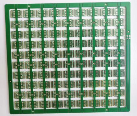
High frequency circuit board
With Rogers materials or other high-frequency materials, the complexity of electronic components and switches is increasing, and faster signal flow is required to improve transmission frequency. Due to the short rise time of electronic components, it is also necessary for high-frequency circuit board/high-speed PCB technology to treat conductor width as electronic components.
According to the different parameters, the high-frequency signal is reflected to the circuit board, which means that the impedance (dynamic resistance) varies with the transmission components. To prevent this capacitive effect, all parameters must be precisely specified and implemented with the highest level of process control.
The key of impedance of high frequency circuit board is the track geometry of conductor, the stacking of layers and the dielectric constant of materials.
High frequency circuit board design process
(1) Transmission line width
The design of transmission line width of high frequency circuit board needs to be based on impedance matching theory.
When the input and output impedance match the transmission line impedance, the system output power is maximum (the total signal power is minimum), and the inlet and outlet reflections are minimum.
For microwave circuit board/RF circuit board/high-frequency microwave RF circuit board, the impedance matching design of PCB circuit board (high-frequency circuit board) also needs to consider the operating point of the device. The signal line through-hole causes the impedance transmission characteristics to change. TTL and CMOS logic signal lines have high characteristic impedance and are not affected.
(2) Crosstalk between transmission lines
When the distance between two parallel microstrip lines is very small, coupling occurs, which leads to crosstalk between lines and affects the characteristic impedance of transmission lines. Special attention shall be paid to 50 ohm and 75 ohm high frequency circuits, and measures shall be taken for circuit design. This coupling feature is also used in actual circuit design, such as mobile phone transmission power measurement and power control. The following analysis applies to high-frequency circuits, ECL high-speed data (clock) lines, and small signal circuits (such as precision operational amplifier circuits).
Set the coupling degree between lines as C, the size of C is equal to ε r. W/d, S is related to the length of parallel line L. The smaller the distance S is, the stronger the coupling is; The longer the L, the stronger the coupling. To increase perceptual knowledge, for example, a 50 ohm directional coupler manufactured using this feature. For example, the 1.97GHz PCS frequency base station power amplifier, where d=30mil, ε r=3.48:
10dB directional coupler PCB size: S=5mil, l=920mil, W=53mil;
20dB directional coupler PCB size: S=35mil, l=920mil, W=62mil.
In order to reduce crosstalk between signal lines, the following suggestions are given:
A. Try to reduce the parallel length between signal lines;
B. High frequency or high-speed data parallel signal line distance S is more than twice the line width.
Use and application range of high frequency board
1、 Definition of PCB high frequency board High frequency board refers to a special circuit board with high electromagnetic induction frequency, which is used in high frequency (frequency over 300MHz or optical wavelength less than 1m) and microwave heating (frequency over 3GHz or optical wavelength less than 0.1m) industries, It is a part of the process flow of using the general stiffness PCB production and manufacturing method on the microwave RF heating copper clad laminate, or a high-frequency PCB produced by using a unique solution. Generally speaking, a high frequency board can be defined as a circuit board with a frequency of about 1GHz.
With the rapid development trend of scientific and technological progress, more and more mechanical equipment are designed to be used in the microwave heating frequency band (>1GHz) and even in the millimeter wave industry (30GHz), which also means that the frequency is getting higher and higher, and the regulations on the boards of high-frequency board circuit boards are getting higher and higher. For example, the raw materials of the base steel plate must have high electrical performance and excellent organic chemical reliability. With the increase of the switching power data signal frequency, the damage on the high-frequency plate is very small, so the necessity of high-frequency plate talent is highlighted.
2、 Classification of high-frequency boards
1. Powder porcelain filling thermosetting type
Raw material A, manufacturer: 4350B/4003CArlon, Rogers, 25N/25FRTaconic, TLG series products B. Production and processing method: similar to the production and processing steps of epoxy resin glue/laminated glass cylinder (FR4), only the plate is relatively brittle, which is very easy to break. The service life of drill tip and gong knife will be reduced by 20% when turning holes and gongs.
2. PTFE
Raw material A: manufacturer 1 RO3000 series products, RT series products, TMM series products, 2Arlon AD/AR series products, IsoClad series products, CuClad series products, 3 3Taconic RF series products, TLX series products, TLY series products, 4 Taixing microwave heated F4B, F4BM, F4BK, TP-2B: production and processing method Cutting: be sure to preserve the protective film cutting materials to avoid scratches, indentation, drilling.
2.1 Use a new and upgraded drill bit (specification 130), one piece at a time is the best, and the working pressure of the presser foot is 40psi;
2.2 The aluminum block is the back cover plate, and then use 1mm melamine tableware cushion block to grasp the PTFE plate;
2.3 After drilling, use a hot air gun to blow out the smoke and dust in the hole;
2.4 Use the most stable drilling machine to rotate the main parameters of the hole (most of them are that the smaller the hole, the faster the drilling speed, and the smaller the Chiload, the smaller the return speed).
4. Pore solution Low temperature plasma solution or sodium naphthalene activity solution is conducive to pore metallization
4. PTH copper deposition
4.1 After micro etching (the micro etching rate is 20 micro feet), the plate is just fed from the hydraulic cylinder at the beginning of PTH pulling. 4.2 If necessary, the plate is fed through the second PTH only from the estimated start.
5. Resistance welding
5.1 Pre solution: use acid and alkali washing instead of grinding with mechanical equipment;
5.2 Solve the problem before baking the plate (90 ℃, 30min), brush green oil and dry it;
5.3 Baked boards in three sections: 80 ℃, 100 ℃ and 150 ℃ in one section for 30min each (if oil is found on the board surface, it can be repaired: wash off the green oil and solve the problem again).
6. Lay the thin paper on the PTFE board road surface, and use FR-4 board with 1.0mm thick etching process to remove copper on the left and right or phenolic resin plate for clamping. The broken edge of the back board of the gong board must be carefully trimmed by hand to resolutely prevent damage to the board and copper surface. Separate the board with very standard sulfur free paper, and watch the inspection. To reduce the burr, the most important thing is to remove the actual effect of the whole process of the gong board.
3、 PCB high-frequency board production process
1. Production and processing steps of NPTH's high-frequency board PTFE board: cutting - hole rotation - dry film - detection - etching process - corrosion inspection - solder resistance - blank mark - tin spraying - forming - detection - final inspection - packaging - delivery
2. PTH's PTFE sheet production and processing steps: cutting - hole rotation - hole solution (low-temperature plasma solution or sodium naphthalene activity solution) - copper deposition - plate electricity - dry film - detection - graphic electricity - etching process - corrosion inspection - resistance welding - space symbol - tin spraying - forming - detection - final inspection - packaging - delivery
3. Green oil process flow: operation of green oil adhesion and green oil bubbling
4. Strictly control surface scratches in each process flow, etc
4、 Main uses of PCB high-frequency board
1. Power amplifier, low noise amplifier, etc;
2. Mobile communication products, intelligent lighting systems;
3. Power divider, coupler, duplexer, filter and other passive components;
4. High frequency of electronic products is the development trend of car anti-collision system software, communication satellite system software, wireless telephone system software and other industries.
5、 High frequency board production and processing problems 1. Copper sinking: it is not easy to copper the hole edge, etching process, the route notch of the graphic boundary, and the manipulation of sand holes. Circuit board manufacturers, circuit board designers and PCBA manufacturers will explain the design process, use and application range of high-frequency circuit boards.


Just upload Gerber files, BOM files and design files, and the KINGFORD team will provide a complete quotation within 24h.