
Professional PCB manufacturing and assembly
Building 6, Zone 3, Yuekang Road,Bao'an District, Shenzhen, China
+86-13410863085Mon.-Sat.08:00-20:00


PCB board heat dissipation design skills
1 Importance PCB thermal design
The electrical energy consumed by electronic equipment during operation, such as RF power amplifiers, FPGA chips, and power products, except for useful work, most of them are converted into heat for dissipation The heat generated by electronic equipment causes the internal temperature to rise rapidly If the heat is not dissipated in time, the equipment will continue to heat, the equipment will fail due to overheating, and the reliability of electronic equipment will be reduced Surface mount technology improves the installation density of electronic equipment and reduces the effective heat dissipation area, while the temperature rise of equipment seriously affects the reliability Therefore, the study of thermal design is very important The heat dissipation PCB of the radiator is a very important link. Let's discuss what the heat dissipation technology of solar cells is For electronic equipment, a certain amount of heat will be generated during operation, making the internal temperature of the equipment rise rapidly If the heat is not dissipated in time, the equipment will continue to heat and become invalid due to overheating The reliability of electronic equipment will be reduced Therefore, it is very important to have a good heat dissipation treatment for the circuit board
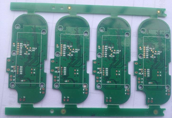
PCB board

2. Analyze PCB temperature risk factors
The direct cause of the temperature rise of the printed board is due to the existence of circuit power consumption devices. Electronic equipment has different degrees of power consumption, and the heating intensity varies with the power consumption
Two phenomena of temperature rise in printed boards:
(1) Local temperature rise or large area temperature rise;
(2) Short-term temperature rise or long-term temperature rise. In the analysis of PCB, the following aspects are generally analyzed
2.1 Electrical power consumption
(1) Analyze the power consumption per unit area;
(2) Analyze the distribution of power consumption on the PCB.
2.2 The structure of the printed board
(1) The size of the printed board;
(2) The material of the printed board
2.3 How to install the printed board
(1) Installation method (such as vertical installation, horizontal installation);
(2) The sealing condition and the distance from the casing.
2.4 Thermal radiation
(1) The emissivity of the printed board surface;
(2) The temperature difference between the printed board and the adjacent surface and their temperature
2.5 Heat conduction
(1) Install the radiator;
(2) Conduction of other installation structures.
2.6 Thermal convection
(1) Natural convection;
(2) Forced cooling convection.
PCB is an effective way to solve PCB temperature rise In products and systems, these factors are often interrelated and dependent Most factors should be analyzed according to the actual situation It can more accurately calculate or estimate specific practical parameters, such as temperature rise and power consumption
3. Some methods PCB thermal design
1. Through PCB itself
At present, PCB boards widely used are copper clad/epoxy glass cloth substrate or phenolic resin glass cloth substrate, and a small amount of paper based copper clad boards are used Although these substrates have excellent power efficiency, processing efficiency and poor heat dissipation As a heat dissipation method for high heat components, it is almost impossible to rely on the heat conduction of PCB resin itself, but to dissipate the heat from the component surface to the surrounding air However, with the electronic products entering the era of miniaturization of components, high-density installation and high heat components, it is not enough to rely only on the surface heat dissipation of components with very small surface area At the same time, due to the large use of surface mount components, such as QFP and BGA, the heat generated by components is transferred to a large amount of PCB Therefore, the solution for heat dissipation is to improve the direct contact between PCB and heating elements and pass through PCB To go out or send out
2. High heat-generating components plus radiator and heat conduction plate
When a small number of components in the PCB generate a large amount of heat (less than 3), you can add a radiator or heat pipe to the heating component When the temperature cannot be reduced, the radiator with fan can be used to enhance the thermal radiation When the number of heating devices is large (more than 3), a large heat dissipation cover (board) can be used, which is a special radiator customized according to the position and height of the heating device on the PCB, or a large flat radiator, which can cut different component height positions The heat dissipation cover is buckled on the surface of the element as a whole, and it contacts with each element for heat dissipation However, the high consistency of components during assembly and welding is poor, and the heat dissipation effect is poor Generally, a soft thermal phase-change heat pad is added on the surface of the element to improve the heat dissipation effect
3. The integrated circuits (or other devices) are arranged vertically or horizontally
4. Use reasonable wiring design to achieve heat dissipation
Because the residue in the plate has thermal conductivity, copper foil wires and holes are good heat conductors, and the new residual rate of copper foil and new heat conduction holes are the main means of heat dissipation To evaluate PCB boards, it is necessary to calculate the equivalent thermal conductivity PCB boards of composite materials composed of various materials with different thermal conductivity
5. The equipment on the same printed board shall be arranged according to its heat value and heat dissipation degree as far as possible Devices with low computational value or poor heat resistance (such as small signal transistors, small integrated circuits, electrolytic capacitors, etc.) should be placed On the upstream (inlet) of the cooling airflow, devices with large heat or heat resistance (such as power transistors, large-scale integrated circuits, etc.) are placed downstream of the cooling airflow
6. In the horizontal direction, the high-power devices are placed as close to the edge of the printed board as possible to shorten the heat transfer path; In the vertical direction, the high-power equipment shall be placed as close to the top of the printed board as possible to reduce the temperature of other equipment during operation Impact
7. The heat dissipation of the printed board in the equipment mainly depends on the air flow. In summary, the air flow path should be studied in the design process, and the equipment or printed circuit board should be reasonably configured When air flows, it always tends to flow at a place with low resistance. In this case, when equipment is installed on the printed circuit board, large airspace should be avoided in a certain area The same problem should also be paid attention to when multiple printed circuit boards are included in the whole machine
8. The temperature-sensitive device is placed in a temperature area (such as the bottom of the device). Do not place it directly above the heating device Multiple devices are arranged on a staggered horizontal plane
9. Power consumption and heating components shall be arranged near the heat dissipation position Do not place high-temperature equipment at the corners and peripheral edges of the printed board unless there is a radiator nearby When designing power resistors, choose larger devices as much as possible, and make them have enough heat dissipation space when adjusting the layout of printed boards
10. RF power amplifier or LED PCB board adopts metal substrate
11. Avoid concentrating hot spots on PCB, evenly distribute power on PCB as much as possible, and keep its surface temperature efficiency uniform and consistent In the design process, it is usually difficult to achieve strict uniform distribution, but areas with high power density must be avoided to prevent hot spots from affecting the normal operation of the entire circuit If possible, it is necessary to analyze the thermal efficiency of printed circuits For example, the addition of thermal performance index analysis software module PCB design software can help designers optimize circuit design
PCB board
4. Summary
4.1 Material selection
(1) The temperature rise of the wires of the PCB due to the passing current plus the specific ambient temperature should not exceed 125 degree Celsius (commonly used typical value. It may be different depending on the selected board) Because the components installed on the PCB will also emit some heat, which will affect the working temperature, these factors should be considered when selecting data and PCB design, and the hot spot temperature should not exceed 125 ℃ Select thicker copper clad laminate as much as possible
(2) In special cases, aluminum base and ceramic base are brittle, and other plates with low thermal resistance can also be selected
(3) Adopting multilayer board structure is helpful for PCB thermal design
4.2 Ensure that the heat dissipation channel is unblocked
(1) Make full use of the components arrangement, copper sheet, window openings and heat dissipation holes to establish a reasonable and effective low thermal resistance channel to ensure the smooth exit of heat from the window PCB
(2) The setting of heat dissipation through holes Design some heat dissipation through holes and blind holes, which effectively increases the heat dissipation area, reduces the thermal resistance, and improves the power density of the circuit board For example, set the through-hole on the pad of LCCC equipment Solder is filled in the circuit production process to improve thermal conductivity The heat generated during circuit operation can be quickly transferred to the metal heat dissipation layer or the copper pad on the back through or blind hole to be dissipated In some specific cases, circuit boards with heat dissipation layers are designed and used professionally Thermal data are usually copper/molybdenum and other data, such as printed boards used on some module power supplies
(3) The use of thermally conductive materials In order to reduce the thermal resistance in the thermal conduction process, heat conduction materials are used on the contact surface between the high power consumption device and the substrate to improve heat conduction efficiency
Solution to Electromagnetic Compatibility of PCB
Nov 10,2022


Just upload Gerber files, BOM files and design files, and the KINGFORD team will provide a complete quotation within 24h.