
Professional PCB manufacturing and assembly
Building 6, Zone 3, Yuekang Road,Bao'an District, Shenzhen, China
+86-13410863085Mon.-Sat.08:00-20:00

Composition and function of SMT head
If the placement machine is a robot, the placement head is a smart manipulator Through program control, the position is automatically corrected, the parts are picked up according to the regulations, and placed on the preset pad accurately to complete the three-dimensional reciprocating motion It is the most complex and critical part of the placement machine The placement head consists of a suction nozzle, a visual alignment system, sensors, and other components
There are two types of placement heads: single head and multi head. The multi head placement head can be divided into fixed type and rotary type. After the suction cup nozzle of the initial single tip mounter attracts a part, the part centering is realized according to the mechanical centering mechanism, and a signal is sent to the feeder to make the next part enter the suction cup position. However, the placement speed of this method is relatively slow, and it usually takes 1s to place the chip modules. In order to improve the patch rate, people have adopted the method of increasing the number of patch headers, that is, using multiple patch headers to improve the patch rate. The multi tip mounter has been increased from single tip to 3. to 6 tips, instead of using mechanical alignment, it has been improved to various forms of optical alignment. Pick up components during work, and then place them on PCB in turn after alignment. At the specified location. At this stage, the patch rate of this model has reached the level of 30000 components per hour. The price of this model is relatively low and it can be used in combination. You can also use a rotating multi head structure. At this stage, the repair rate of this method has reached 45000 to 50000 pieces per hour.
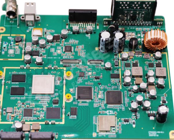
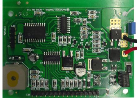
Circuit board

(1) Suction nozzle. At the end of the placement head, there is a placement tool controlled by the vacuum pump, namely the suction nozzle. Parts of various shapes and sizes are usually picked and placed using various suction nozzles. After the vacuum is generated, the negative pressure of the suction nozzle sucks the SMD components from the feeding system (bulk silos, tubular hoppers, disk tape or pallet packaging). The suction nozzle needs to reach a certain vacuum degree during film suction. Only in this way can we judge whether the picked parts are normal. When the part is side standing or cannot be sucked out due to the part "cylinder", the mounter will give an alarm signal. When picking a nozzle pick component and placing it on a PCB, two methods are usually used for placement. One is based on the height of the component, that is, the thickness of the component is input in advance. When the placement head is lowered to this height, release the vacuum and place the component on the pad. When using this method, due to individual differences of components or PCBs, early or late placement may occur, and in serious cases, component displacement or flyer defects may result. Another more professional method is based on the transient response of components and PCBs to achieve soft landing under the action of pressure sensors. This is easy to place, not easy to cause displacement and flying chip defects.
The suction nozzle is a direct contact SMT assembly In order to adapt to the placement of various components, many mounters will also be equipped with equipment for removing and replacing suction nozzles There is also elastic compensation between the suction nozzle and the suction tube The buffer mechanism ensures protection of the patch assembly during picking
In the process of high-speed movement, the nozzle contacts with the components, and its wear is very serious. In this case, the data and structure of suction nozzle become more and more important. In the early days, alloy materials were used, and then carbon fiber wear-resistant plastic materials were used. The more professional nozzle uses ceramic materials and diamonds to make the nozzle more durable.
With the miniaturization of SMT components and the reduction of the clearance between SMT components and surrounding components, the structure of the nozzle has been relatively adjusted. A hole is opened on the suction nozzle to ensure stability when picking up small parts such as 0603. It is easy to install and place without affecting the surrounding components.
(2) Visual calibration system. With the increasing demand for small, light, thin and high reliability of electronic products, the reliability of surface mounting can only be ensured by precisely placing the fine pitch components. In order to install the fine pitch components accurately, the following factors should be considered.
1. PCB positioning deviation. Under normal circumstances, the circuit pattern on the PCB does not always correspond to the PCB mechanical positioning and the machining hole on the PCB edge, which will lead to installation deviation. In addition, defects such as circuit pattern deformation, PCB deformation and warping on PCB will lead to installation deviation.
2. Alignment deviation of components. The center line of the component itself does not always correspond to the center line of all the leads. In addition, when the placement system uses a mechanical centering claw to center the component, the center line of all the leads of the component may not be aligned. In addition, in the packaging container, or when the centering claw is clamped and centered, the component leads may be bent, twisted and overlapped, that is, the leads lose coplanarity. This phenomenon will lead to placement deviation and reduce placement reliability. When the component lead deviates from the pad by no more than 25% of the lead width, the surface mounting is successful. When the lead spacing is narrow, the allowable deviation is small.
3. Motion deviation of the machine itself Mechanical factors affecting placement accuracy include: X-Y axis movement accuracy of placement head or PCB positioning table, SMT component centering mechanism accuracy and placement accuracy The vision system has become an important part of high precision placement machine


Just upload Gerber files, BOM files and design files, and the KINGFORD team will provide a complete quotation within 24h.