
Professional PCB manufacturing and assembly
Building 6, Zone 3, Yuekang Road,Bao'an District, Shenzhen, China
+86-13410863085Mon.-Sat.08:00-20:00

1 Why digital and analog
Because even though it's connected, it's different when the distance is longer. The voltage at different points of the same wire may be different, especially when the current is high. Because the wire has resistance, there is a voltage drop when the current flows through it. In addition, the wire has a distributed inductance, the effect of which will be shown in AC signals. So we have to divide it into digital and analog, because the high frequency noise of the digital signal is very loud, and if you mix the analog and the digital, it will spread the noise to the analog part and cause interference. If the ground is separated, the high-frequency noise can be isolated by filtering at the power source. But if you mix the two, it's hard to filter.
2. How to design digital ground and analog ground
Two basic principles of electromagnetic compatibility (EMC) must be understood before design: the first principle is to minimize the area of the current loop; The second principle is that the system uses only one reference plane. Conversely, if the system has two reference surfaces, a dipole antenna may be formed (note: the radiation of a small dipole antenna is proportional to the length of the line, the amount of current flowing, and the frequency); If the signal does not return through the smallest possible loop, it may form a large loop antenna (note: the radiation of a small loop antenna is proportional to the area of the loop, the size of the current flowing through the loop, and the square of the frequency). Try to avoid both in your design.
It has been suggested that the digital and analog parts of the mixed-signal circuit board be separated to achieve isolation between the digital and analog parts. Although this approach is feasible, there are many potential problems, especially in complex and large systems. The most critical problem is not to cross the divide gap wiring, once across the divide gap wiring, electromagnetic radiation and signal crosstalk will increase sharply. The most common problem in PCB design is EMI problem caused by signal lines crossing the ground or power supply.

We use the above segmentation method, and the signal line crosses the gap between the two places, what is the return path of the signal current? Assuming that the two separated ground are connected at some point (usually a single point of connection at some point), in this case the ground current will form a large loop. The high frequency current flowing through the large loop generates radiation and very high ground inductance. If the low level analog current flowing through the large loop, the current is easily interfered by external signals. Worst of all, when the strips are connected together at the power source, they create a very large current loop. In addition, analog and digital are connected together by a long wire to form a dipole antenna.
Understanding the path and mode of current backflow to ground is the key to optimize the design of mixed signal circuit board. Many design engineers consider only where the signal current flows, ignoring the exact path of the current. If the ground layer must be divided and routed through the gap between the divisions, a single point connection can be made between the divided ground first to form a bridge between the two ground, and then routed through the bridge. In this way, a direct current return path can be provided under each signal line, so that the loop area formed is small.
Optical isolation devices or transformers can also be used to realize the signal across the segmentation gap. For the former, it is the optical signal that crosses the segmentation gap; In the case of transformers, it is the magnetic field that crosses the split gap. It is also possible to use differential signals: signals flow in from one line and return from another, in which case they do not need to be used as a return route.
To investigate the interference of digital signal to analog signal, we must first understand the characteristics of high frequency current. High frequency currents always choose the path with the lowest impedance (lowest inductance), directly below the signal, so that the return current flows through the adjacent circuit layer, whether the adjacent layer is the power layer or the ground layer. In practice, it is generally preferred to use a unified PCB partition into analog parts and digital parts. Analog signals are routed in analog areas in all layers of the board, while digital signals are routed in digital circuits. In this case, the digital signal return current does not flow into the analog signal.
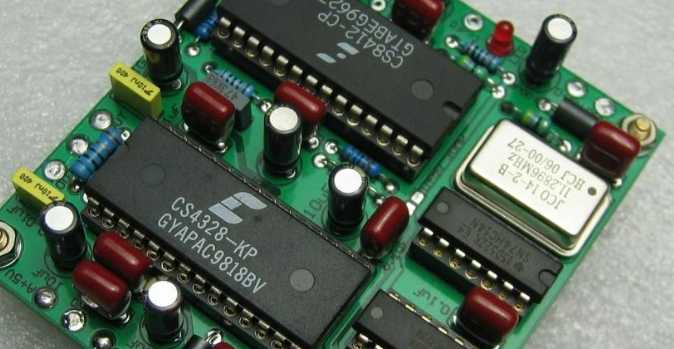
Signal PCB board
Mar 21,2023


Just upload Gerber files, BOM files and design files, and the KINGFORD team will provide a complete quotation within 24h.