
Professional PCB manufacturing and assembly
Building 6, Zone 3, Yuekang Road,Bao'an District, Shenzhen, China
+86-13410863085Mon.-Sat.08:00-20:00

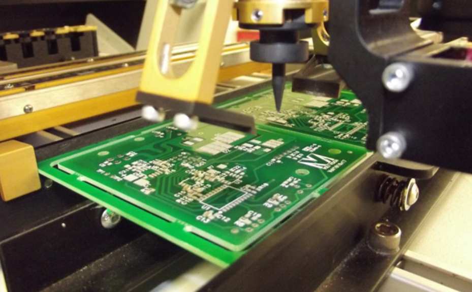
Reliability failure analysis of SMT electronic assembly is an important part in the reliability work of electronic assembly process. It is necessary to have certain testing and analysis equipment to carry out the failure analysis of electronic process. All kinds of analytical equipment have their performance characteristics, application range and sensitivity. According to the requirements and requirements of failure analysis, it is necessary to adopt various analysis techniques and methods to determine the location of failure, the degree of failure, the cause and mechanism of failure. So failure analysis is related to a lot of professional knowledge of the analysis theory, but also related to a variety of analysis devices, analysis experience in failure analysis also plays a very important role. Failure analysis of electronic assembly process investigation and analysis of failure situation, identification of failure modes, description of failure characteristics, hypothesis and determination of failure modes, as well as corrective measures and prevention of new failures.
Failure analysis of electronic assembly process is to conduct post-inspection and analysis of failure phenomena related to assembly process, such as solder joints, through holes and wiring, which are judged to be failures according to performance failure criteria. The purpose is to discover and determine the failure causes and mechanisms related to assembly process, so as to feed back to the designer, manufacturer and user to prevent failure from happening again. To achieve the ultimate purpose of improving the reliability of electronic products.
The functions of electronic assembly process failure analysis are as follows:
1, Through failure analysis to improve the hardware design, process design and reliable application of the theory and method.
2. Through failure analysis, the physical phenomenon causing the failure is found, and the reliability prediction model is obtained.
3. Provide theoretical basis and practical analysis means for reliability test (accelerated life test and screening test) conditions.
4. When processing process problems encountered in the process, determine whether they are batch problems and provide basis for batch recall and scrapping.
5. Corrective measures through failure analysis can improve the yield and reliability of electronic products, reduce the failure of electronic products during operation, and obtain obvious economic benefits.
The techniques and methods for failure analysis of electronic assembly process include appearance inspection, metallographic section analysis, optical microscope analysis, infrared microscope analysis, acoustic microscope analysis, scanning electron microscope, electron beam testing, X-ray analysis, dyeing and penetration testing, etc. In the application of failure analysis, one or more of these technologies should be comprehensively used according to the types, phenomena and mechanisms of failure problems to complete the failure analysis work. This chapter mainly introduces the principle, method and application of the frequently used analysis techniques in electronic assembly process failure analysis.
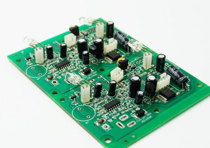
Appearance inspection mainly analyzes and checks appearance defects. The purpose of appearance inspection is to record the physical size, material, design, structure and marking of PCB components and solder joints, confirm appearance damage, detect contamination and other anomalies and defects. These problems are evidence of errors, overload and operation errors caused by process manufacturing or application, and these information may be related to failure.
Visual examination is usually done by eye examination, but can also be done with 1.5 to 10 magnifying glass or light microscope. One of the functions of appearance inspection is to verify the conformity of process failure printed circuit boards, components and solder joints with standards and specifications; The second function of the appearance inspection is to look for problems that may cause failure. For example, cracks in the casing or glass insulators may be caused by external ambient gases entering the components and causing changes in electrical properties or corrosion. If there is a foreign body between the outer leads, the foreign body may cause a short circuit between the leads. Mechanical damage on PCB surface may lead to PVB line breakage and open circuit.
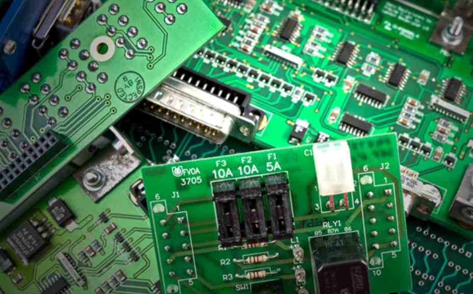
Since the failure analysis may have to do the destructive analysis such as slicing and deencapsulation, the object of appearance inspection no longer exists, so it is necessary to make detailed records and preferably take some pictures during the appearance inspection. As a preliminary check, valuable information may be lost if the specimen is treated carelessly before the appearance is examined. As a part of the appearance inspection procedure, all information marking shall be recorded first, that is, the manufacturer name, specifications, models, batches, date codes and other information of PCB manufacturer and component manufacturer shall be recorded in detail. Secondly, special attention should be paid to the following aspects of the content of the inspection.
1. Mechanical damage: cracks, scratches and defects of pins, roots and sealing joints of electronic components; Solder joints and PCB surface mechanical damage marks.
2. Device sealing defects: the joints between the pins of electronic components and glass, ceramics and plastics, as well as the adhesive parts and sealing joints of the roots.
3. Device pin coating defects: uneven coating, bubbles, pinholes and rust from the surface of electronic components.
4. PCB surface contamination or adhesion: mainly from the processing process.
5. Thermal or electrical damage of the device.
6, PCB layering and bursting, etc.
7. Abnormal surface treatment layer of PCB board.
8. Whether the solder joint is remelted and cracked.
In the reliability design, it is necessary to put forward clear control requirements for the production, storage, storage and transportation process in the process document, and the suspicious part must be further inspected by measuring instruments that can obtain information. Stereo microscopes have high microscopic observation and simple low magnification, the magnification between the two (about several times to 150 times). High magnification metallographic microscope can be used not only for clear field observation, but also for dark field observation and differential interference observation. The magnification can be from tens of times to about 1500 times. In addition, if you need to make the depth of field of view, there is a scanning electron microscope, the magnation of tens to tens of thousands of times, resolution from a few mm to about 15nm, is an indispensable device to observe the specimen with a fine structure. All important information is recorded photographically using a microscope and its photographic appendages.


Just upload Gerber files, BOM files and design files, and the KINGFORD team will provide a complete quotation within 24h.