
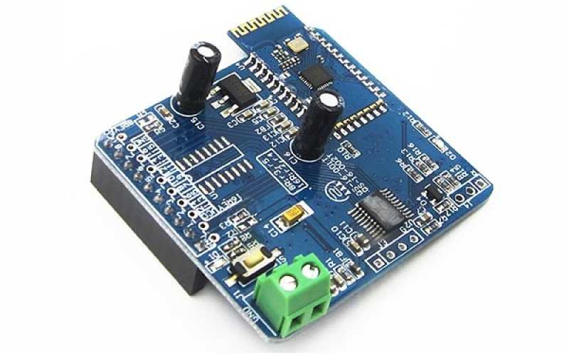
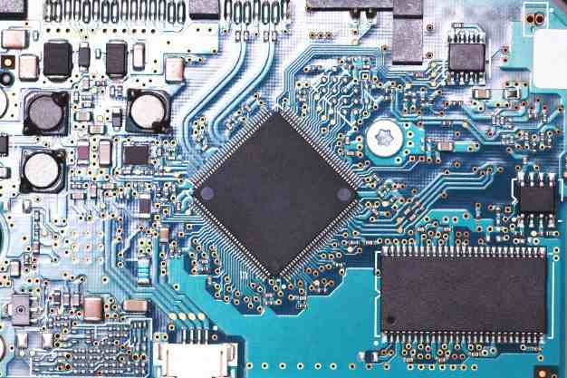
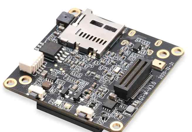
Professional PCB manufacturing and assembly
Building 6, Zone 3, Yuekang Road,Bao'an District, Shenzhen, China
+86-13410863085Mon.-Sat.08:00-20:00

On printed circuit boards, copper is used to interconnect the components on the substrate. Although it is a satisfactory conductor material to form the pattern of the conductive path of printed circuit boards, if exposed to air for a long period of time, it is easy to miss gloss due to oxygenation and miss soldering due to corrosion. Because of this, it is important to take care of copper printing wire, through hole and plating through hole with a variety of techniques, including organic coating, oxygenated film and electroplating techniques. Organic coating application is very simple, but because of the change of liquid concentration, composition and curing period, it is uncomfortable to use for a long period of time, and it even causes the welding resistance can not be predicted in advance. The oxygenated membrane may try to protect the circuit from denudation, but it may not maintain weldability. Electroplating or metal coating processes are standard operations for ensuring weldability and taking care of the circuit to prevent denudation. They play an important role in the manufacture of single, double and multilayer circuit boards. In particular, it has become a standard operation for copper wire to be coated with a sintered metal.
The interconnection of various plates in electronic facilities often requires the use of printed circuit board (PCB) plug sockets with spring contacts and a matching preset printed circuit board with connected contacts. These contacts should have a high wear resistance and a very low connection resistance, which requires a layer of metal plated on it, which is the most commonly used metal is gold. Additional on the printing line can also be used other coated metal, such as tin plating, plating town, sometimes can also be printed in some areas of copper plating.
An additional coating on the copper printing line is an organic compound, which is generally a weld-proof film. In those places where welding is not necessary, a layer of epoxy gas natural resin film is covered with screen printing technology. The process, which is coated with an organic flux, does not require electron exchange. When the PCB circuit board is immersed in a chemical bath, a nitrogen-tolerant compound can stand on the exposed metal surface and not be copied by the substrate.
The precise technology required by electronic products and the strict requirements of background and safety suitability have promoted the great progress of electroplating practice, which is manifested in the production of multi-substrate technology with high complexity and high defense rate. In electroplating, the technology has reached an astounding level with the development of semi-automated, computer-controlled electroplating facilities, the development of highly sophisticated instrumentation for the chemical profiling of organic compounds and metal additives, and the emergence of techniques for the very accurate suppression of chemical reaction processes.
There are two standard ways to make the metal layer grow in the circuit board wire and through hole: line plating and full plate copper plating, described below.
1. Line plating
The process only accepts the formation of copper layers and the corrosion blocking agent metal plating where the circuit pattern and through-hole are preset. In the process of line plating, the increased width of each side of the line and welding pad is roughly equivalent to the increased thickness of the plating surface, because of this, the need to leave a margin on the original plate.
In line plating basically most of the copper surface should be implemented blocking agent hiding, only in the line and welding pad and other circuit graphic place electroplating. Because the surface area of the required plating is reduced, the required power current volume is generally greatly reduced. Additionally, when using a reverse photosensitive polymer dry film plating inhibitor (the most commonly used type), the negative substrate can be manufactured with a relatively inexpensive laser printer or pen. The anode consumes less copper in line electroplating, and less copper needs to be removed in the process of etching, because this reduces the cost of analysis and protection of the electrolytic cell. The deficiency of this technique is that the circuit graphics need to be coated with tin/lead or an electrophoretic resistance material prior to etching and removed before applying the welding resistance. This adds complexity and an additional set of wet chemical solution disposal processes.
2. All plates are plated with copper
In this process, all surface areas and boreholes are plated with copper. A little resistance is poured on the surface of unnecessary copper, and then the corrosion resistance metal is plated. Even for a medium-size printed circuit board, this requires the ability to provide considerable electrical current, enough to produce an easy-to-clean, smooth, shiny copper surface for subsequent processes. If there is no photoplotter, then the need to use a negative plate to expose circuit graphics, so that it becomes more common compared to reverse dry film photoresist.


Just upload Gerber files, BOM files and design files, and the KINGFORD team will provide a complete quotation within 24h.