
Professional PCB manufacturing and assembly
Building 6, Zone 3, Yuekang Road,Bao'an District, Shenzhen, China
+86-13410863085Mon.-Sat.08:00-20:00


What is the SMT mounting principle?
SMT patch refers to the abbreviation of a series of technological processes processed on the basis of PCB, and PCB is a printed circuit board SMT is surface mount technology (Surface Mounted Technology) (abbreviation for Surface Mounted Technology), which is the most popular technology and process in the electronic assembly industry
SMT mounters are commonly referred to as surface mount technology. They are usually used to mount electronic components on PCB boards, as well as LED beads and SMT components. They are used in SMT production lines to improve productivity and replace equipment that saves labor costs.
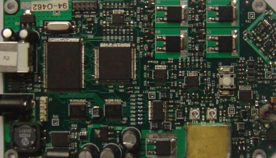
Circuit board

The whole SMT production line includes three processes: screen printing, component placement and reflow soldering Installation is an important part of the whole surface installation process Therefore, the SMT machine is the equipment with the largest investment and production in the whole SMT production line Key and most complex equipment
SMT is actually a kind of precision industrial robot, which is a combination of electromechanical, optical and computer control technologies. By absorbing displacement, positioning and placing functions, SMC/SMD components can be quickly and accurately installed to the designated pad position on PCB without damaging components and PCB. There are three methods for component alignment: mechanical alignment, laser alignment, and visual alignment.
The placement machine is composed of a frame, xy motion mechanism (ball screw, linear guide rail, drive motor), placement head, component feeder, PCB bearing mechanism, component centering detection device and computer control system. The motion is mainly realized by xy motion mechanism, the power is transmitted by ball screw, and the direction motion is realized by rolling linear guide rail motion pair. This type of transmission not only has small motion resistance, compact structure and high motion accuracy. Ensure the placement accuracy of each component.
The mounter is marked on important parts, such as the mounting spindle, moving/stationary lens, nozzle support and feeder. Machine vision can automatically calculate the coordinates of these marking center systems, establish the conversion relationship between the placement machine system coordinate system and PCB and placement component coordinate system, and calculate the precise coordinates of the placement machine movement; The placement head grabs the nozzle and sucks the component according to the package type, component number and other parameters of the imported placement component to the corresponding position.
Static camera detection, identifying and aligning the picking components according to the visual processing program; After the calibration is completed, the placement head installs the assembly to the position on the PCB at the predetermined position This series of components are identified and centered. After the industrial computer obtains the relevant data according to the corresponding instructions, the control system will instruct and automatically complete the inspection and placement actions
Patch nozzle type and patch market witness
Dec 01,2022


Just upload Gerber files, BOM files and design files, and the KINGFORD team will provide a complete quotation within 24h.