
Professional PCB manufacturing and assembly
Building 6, Zone 3, Yuekang Road,Bao'an District, Shenzhen, China
+86-13410863085Mon.-Sat.08:00-20:00

Rework and replace wafer components during SMT processing
SMT refers to surface mount technology, also known as surface mount technology or surface mount technology, which is a popular technology and process in the electronic assembly industry
Under normal circumstances, the electronic products used are designed by PCB plus various capacitors, resistors and other electronic components according to the designed circuit diagram. All kinds of electrical appliances need various smt chip processing technologies to process.
The basic process flow of smt includes solder paste printing, part placement, reflow soldering, AOI optical inspection, maintenance and plate separation.
SMT chip processing technology can save data, energy, equipment, manpower, time, etc., and greatly reduce costs. Today, electronic products are processed through SMT.
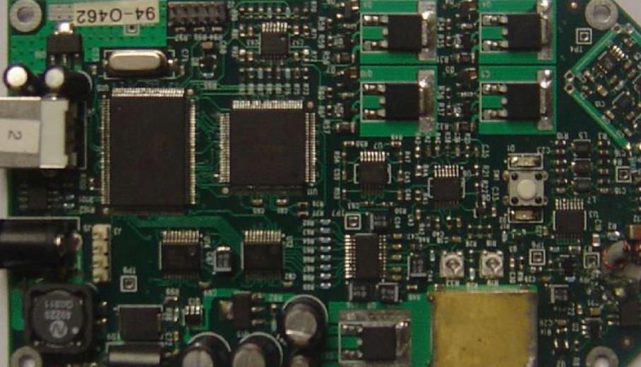
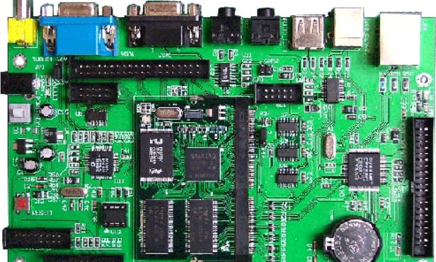
Circuit board

In the SMT process and maintenance, the chip module is one of the more contact information In the SMT processing, the chip components need to be replaced from time to time Replacing a chip module seems very simple, but there are still many tricks If you don't pay attention, the operation is still very troublesome In order to ensure the product quality, you need to replace the chip components in strict accordance with the relevant requirements
Before replacing wafer components in SMT processing and maintenance, it is necessary to prepare a grounded and temperature controllable electric soldering iron. The width of the tip of the soldering iron must match the size of the metal end face of the chip module. The soldering iron needs to be heated to 320 ℃. In addition to electric soldering iron, you also need to prepare some basic tools, such as tweezers, tin bars, fine low-temperature rosin and welding wire.
When replacing, place the soldering iron head directly on the upper surface of the damaged part. When the solder on both sides of the part and the adhesive below it melt, use tweezers to remove the part. Next, remove the residual tin on the circuit board with a tin removal strip, and then wipe the adhesive and other stains on the original pad with alcohol.
Generally, only a proper amount of solder is applied to a pad on the circuit board; Then place the assembly on the mat with tweezers. In order to quickly heat the tin on the bonding pad, it is necessary to place the melted tin contact chip assembly on the metal end, but do not contact the assembly with the tip of the soldering iron.
It should be noted that as long as one end of the newly replaced chip assembly is fixed, the other end can be welded, but more attention should be paid to heating the PCB pad on the floor and adding a proper amount of solder to form a bright arc between the pad and the component end face The amount of solder shall not be too much to prevent it from flowing to the bottom of the part and short circuiting the gasket; For the same reason, during welding, only molten tin can be immersed in the metal end of the part, and the tip of the soldering iron should not contact the part to complete the whole replacement process.
Principle of SMT chip function tester
Dec 01,2022


Just upload Gerber files, BOM files and design files, and the KINGFORD team will provide a complete quotation within 24h.