
Professional PCB manufacturing and assembly
Building 6, Zone 3, Yuekang Road,Bao'an District, Shenzhen, China
+86-13410863085Mon.-Sat.08:00-20:00


Classification of Mark Points in PCB Design
1) Mark points are used for optical positioning during solder paste printing and component placement. According to the role of Mark points on, it can be divided into panel Mark points, board Mark points, and local Mark points (also called device level MARK points)
2) There should be at least three Mark points on the process edge of the panel and on the veneer without panel, which are distributed in L-shape, and the diagonal Mark points are asymmetric about the center
3) If there are mounted components on both sides, there should be Mark points on each side.
4) The boards that need to be spliced should have Mark points as much as possible. If there is no place for Mark points, you can not place Mark points on the boards.
5) For QFP with lead wire center distance ≤ 0.5 mm and BGA with lead wire center distance ≤ 0.8 mm and other devices, local Mark points shall be set on the diagonal near the diagonal passing through the center point of the component to facilitate accurate positioning.
6) If several SOP devices are relatively close (≤ 100mm) to form an array, they can be considered as a whole, and two local Mark points can be designed at their diagonal positions.
PCB design
PCB design description and size requirements:
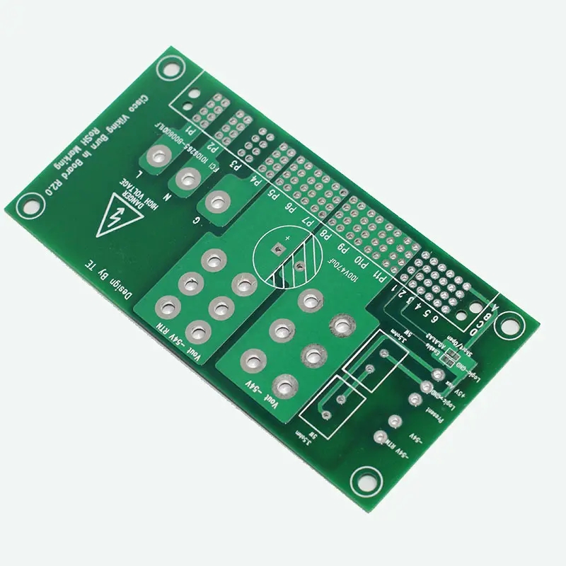
1) The shape of the mark point is a solid circle with a diameter of 1mm. The material is copper and the surface is sprayed with tin. Pay attention to the flatness, the edges are smooth and neat, and the color is obviously different from the surrounding background color; The resistance welding window is concentric with the Mark point. The diameter of the panel and veneer is 3mm, and the diameter of the local Mark point is 1mm
2) The center of the Mark point on the veneer shall be no less than 5mm from the edge of the veneer; The center of the Mark point on the PCB process edge shall be no less than 3mm from the board edge.
3) In order to ensure the recognition effect of printing and, there should be no pads, vias, dots, routing, silk screen marks, etc. within the range of Mark points, which cannot be cut by V-CUT slot to make the machine unrecognizable.
4) To increase the contrast between the Mark point and the substrate, copper foil can be laid under the Mark point. The inner background of the Mark point on the same board should be the same, that is, whether there is copper foil under the Mark point should be the same.
5) Mark points of PCB boards and panels shall be designed as components, and local mark points shall be designed as a part of PCB component packaging. It is convenient to assign accurate coordinate values for positioning.


Just upload Gerber files, BOM files and design files, and the KINGFORD team will provide a complete quotation within 24h.