
Professional PCB manufacturing and assembly
Building 6, Zone 3, Yuekang Road,Bao'an District, Shenzhen, China
+86-13410863085Mon.-Sat.08:00-20:00

Nowadays, more and more surface mounting is used. Compared with traditional packaging, it can reduce the total area of circuit boards, facilitate the production and processing of large numbers of PCBs, and has high relative density of PCB routing. The lead inductance of SMD resistors and capacitors is greatly reduced, which has great advantages in high-frequency circuits. The inconvenience of surface mount components is not conducive to manual welding. Therefore, the circuit board welding technical engineer takes the general PQFP package chip as an example to introduce the basic welding process of surface mount components in detail.
1、 Required special tools and raw materials
The welding tools must have 25W copper head small soldering iron, Jinqiao electrode, a standard applicable temperature adjustable welding table with ESD maintenance, and pay attention to the tip of the soldering iron should be thin, and the total width of the top should not exceed mm. A sharp mouth medical forceps can be used to move and fix the fixed chip and check the power circuit. Fine electrodes, fluxes, isopropyl alcohol, etc. shall also be prepared in advance. The purpose of applying flux is to improve the flowability of soldering tin, so that soldering tin can be pulled with a soldering iron and coated on the pins and solder layers with the help of surface tension. After welding, remove the welding flux on the plate with ethanol.
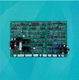
Welding and processing of circuit board
2、 PCB welding process
1. The technical engineer reminds the readers to apply flux on the welding layer before welding, and solve it with a soldering iron once to prevent poor tin plating or oxidation of the welding layer, which may lead to poor soldering, and the chip generally does not need to be solved.
2. Use medical tweezers to carefully put PQFP chip onto PCB board, and be careful not to damage pins. Align it with both ends of the solder layer, and ensure that the chip is placed in the right position. Adjust the temperature of the soldering iron to more than 300 ℃, dip a small amount of solder on the tip of the soldering iron, press the chip at the pointed position down with a special tool, add a small amount of flux to the pins at the two top corners, still press the chip down, and solder the pins at the two top corners, so that the chip is fixed and cannot be moved. After welding the top corner, check again whether the chip is pointing. If necessary, it can be adjusted or disassembled and pointed on the PCB again.
3. At the beginning of welding all the pins, solder should be added to the tip of the soldering iron, and all the pins should be coated with flux to keep the pins moist. Touch the end of each pin of the chip with the tip of the soldering iron until you see the solder injected into the pin. During welding, keep the soldering iron tip and the pin to be welded in parallel to avoid overlapping of reinforcement due to excessive soldering tin.
4. After welding all the pins, wet all the pins with flux to facilitate soldering tin cleaning. Unnecessary soldering tin shall be removed in necessary areas to remove all short circuit faults and rebar overlapping. Finally, use medical tweezers to check whether there is false connection. After the inspection, remove the flux from the circuit board, soak the hard brush with ethanol and carefully scrub along the pin direction until the flux disappears.
5. The circuit board welding technical engineer reminds you that the chip mounted RC components are relatively easy to solder. First, tin a spot weld, then place one end of the component, pinch the PCB components with medical tweezers, and then check whether it is adjusted after welding one end; If it has been adjusted, weld the other end. In order to truly grasp the welding skills, a lot of practical activities must be carried out.
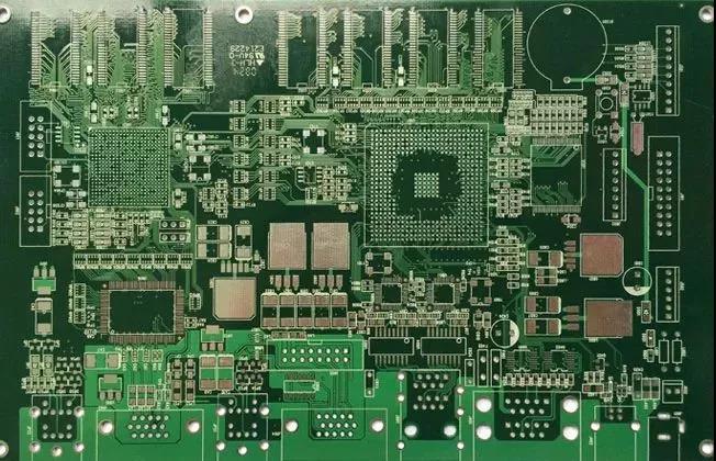
Batch Proofing Production of High Precision PCB
Nov 07,2022


Just upload Gerber files, BOM files and design files, and the KINGFORD team will provide a complete quotation within 24h.