
Professional PCB manufacturing and assembly
Building 6, Zone 3, Yuekang Road,Bao'an District, Shenzhen, China
+86-13410863085Mon.-Sat.08:00-20:00

Signal Reflow and Cross Segmentation in High Speed PCB
Regarding the signal return and cross segmentation in high speed PCB. Here we simply construct a "scene", ground return, and introduce power return and some cross segmentation problems in combination with the figure below In order to facilitate drawing, the layer spacing is increased
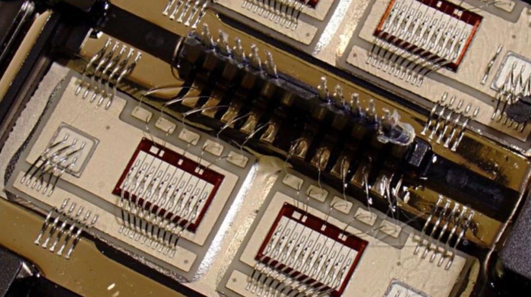
PCB board

IC1 is the signal input terminal (to simplify the PCB model, it is assumed that the receiving terminal contains a lower connection resistance) The third layer is the bottom layer IC1 and IC2 are grounded from the third ground plane The upper right corner of the top floor is a power plane, which is connected to the positive pole of the power supply C1 and C2 are decoupling capacitors of IC1 and IC2, respectively The power and ground pins of the chip shown in the figure are the power and ground of the transmitting and receiving signal terminals In case of low frequency, if S1 terminal outputs high level, the whole current loop connects the power supply to VCC power plane through wires, then enters IC1 through the orange path, exits from S1 terminal, and enters IC2 through R1 terminal along the second layer of wires, then enters GND layer, and returns to the negative pole of power supply through the red path
However, at high frequencies, the distribution characteristics of PCB will have a great impact on the signal The ground echo is a common problem in high frequency signals When the current from S1 to R1 in the signal line increases, the external magnetic field changes rapidly, which will generate a reverse current in the nearby conductor If the ground plane of the third floor is a complete ground plane, there will be a current marked by a blue dotted line on the ground plane; If there is a complete power plane on the top floor, the current will also flow back along the blue dot At this time, the signal loop has a current loop, which radiates energy to the outside and has the ability to couple external signals (The skin effect at high frequencies also radiates energy outward, the principle is the same.)
Since the high frequency signal level and current change rapidly, but the change period is very short, and the energy required is not very large When C1 is large enough and the response is fast enough (with very low ESR value, ceramic capacitors are usually used, the orange path on the top layer and the red path on the GND layer can be It is regarded as non-existent (there is a current corresponding to the power supply of the whole board, but not the current corresponding to the signal shown in the figure).
PCB board
Therefore, according to the environment built in the figure, the entire path of the current is: from the positive pole of C1 ->VCC of IC1 ->S1 ->L2 signal line ->R1 ->GND of IC2 ->via hole ->$of the GND layer Path ->Via ->Capacitor Negative It can be seen that there is a brown equivalent current in the vertical direction of the current, and a magnetic field will be generated in the middle At the same time, the ring can be easily coupled with external interference If the signal in the figure is a clock signal, there is a group of parallel 8-bit data lines powered by the same power supply of the same chip, and the current return path is the same If the data lines flip in the same direction at the same time, the clock will sense a large reverse current If the clock lines do not match, this crosstalk is enough to have a fatal impact on the clock signal The strength of this crosstalk is not proportional to the level of the interference source, but is proportional to the current change rate of the interference source For pure resistance load, crosstalk current is proportional to dI company/dt=dV/(T10% - 90% * R) In the formula, dI/dt (current rate of change), dV (swing of the interference source) and R (interference source load) all refer to the parameters of the interference source (if it is a capacitive load, dI/dt is related to T10%, and 90% square is inversely proportional) It can be seen from the formula that the crosstalk of low-speed signals is not necessarily less than that of high-speed signals This is what we said: the 1kHZ signal is not necessarily a low-speed signal, and the edge condition should be considered comprehensively For signals with very steep edges, it contains many harmonic components and has a large amplitude at each octave point Therefore, attention should also be paid to the selection of equipment Don't blindly select chips with fast switching speed. This is not only costly, but also will add crosstalk and EMC problems
Any adjacent power plane or other planes with appropriate capacitors on the signal to provide a low reactance path to GND can be used as the return plane of the signal In general applications, the corresponding chip IO power supply of the transceiver is usually the same, usually 0.01-0.1uF decoupling capacitors between each power supply and the ground. These capacitors are also at both ends of the signal. Therefore, the return effect of the power plane is only inferior to the ground plane When other power planes are used for return current, there is usually no low reactance grounding path at both ends of the signal With this kind of pipe, the current induced in the adjacent plane will find the capacitance closest to the ground If the "near capacitor" is far from the starting point or the end point, the return flow must go through a "long journey" to form a complete return path, which is also the return path of adjacent signals The influence of the same return path and common ground interference is the same, which is equivalent to the crosstalk between signals
A high pass filter (such as a 10 ohm resistor series 680p capacitor) can be connected across a capacitor or a RC series connection at the cross segmented place The specific value depends on your own signal type, that is, to isolate low frequency crosstalk between the mutual planes) This may involve adding capacitors between power planes, which may seem funny, but it does work If some specifications do not allow, the capacitor can be grounded on two planes at the split point In case of borrowing other aircraft to return, several small capacitors can be appropriately added on the ground at both ends of the signal to provide a return path But this method is usually difficult to implement Because most of the surface space near the terminal is occupied by the matching resistance and decoupling capacitance of the chip
he above is the explanation given by the editor of pcb circuit board company.
If you want to know more about PCBA, you can go to our company's home page to learn about it.
In addition, our company also sells various circuit boards,
High frequency circuit board and SMT chip are waiting for your presence again.

Causes and Solutions of PCB Welding Defects
Nov 07,2022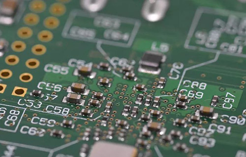


Just upload Gerber files, BOM files and design files, and the KINGFORD team will provide a complete quotation within 24h.