
Professional PCB manufacturing and assembly
Building 6, Zone 3, Yuekang Road,Bao'an District, Shenzhen, China
+86-13410863085Mon.-Sat.08:00-20:00


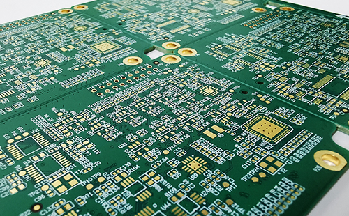
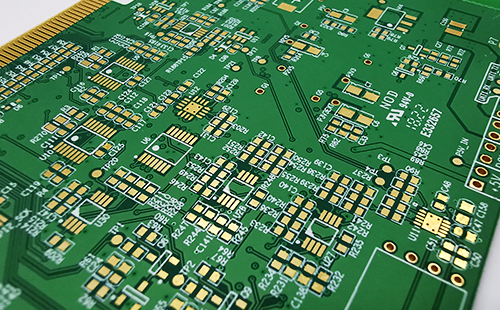
Precautions related to PCB board layout
Capacitor fault
The failure caused by capacitor damage is in the electronic equipment of PCB board, especially the electrolytic capacitor Capacitor damage is characterized by capacity reduction, complete loss of capacity, leakage, and short circuit The functions of capacitors in circuits are different, and the faults they cause have their own characteristics: in industrial control circuit boards, digital circuits account for the vast majority, capacitors are mainly used for power filtering, and fewer capacitors are used for signal coupling and oscillation circuits If the electrolytic capacitor used in the switching power supply is damaged, the switching power supply may not vibrate and has no voltage output; Or the output voltage is not filtered well, because the voltage is unstable and the circuit logic is disordered, it is good or bad when the machine is working or turned on If the capacitor is connected between the positive and negative poles of the digital circuit power supply, the fault is the same as above This is particularly evident on the computer motherboard Many computers have been used for several years, sometimes they cannot be opened, sometimes they can be opened again When you open the box, you can often see the phenomenon of electrolytic capacitor bulging If the capacitor is removed, measure the capacity, It was found to be much lower than the actual value The life of capacitor is directly related to the ambient temperature The higher the ambient temperature, the shorter the life of the capacitor This rule applies not only to electrolytic capacitors, but also to other capacitors Therefore, when looking for a faulty capacitor, you should focus on the capacitor near the heat source, such as the capacitor next to the radiator and high-power components The closer you are to them, the greater the possibility of damage Therefore, pay attention to maintenance and search Some capacitors leak seriously, and even burn hands when touching with fingers These capacitors must be replaced In case of good and bad faults during maintenance, most faults are caused by capacitor damage, except for the possibility of poor contact Therefore, you can concentrate on checking the capacitor in case of such faults This is often surprising after replacing capacitors
Resistor fault
It is often seen that many beginners will leave resistors aside when repairing circuits, disassembling and welding. In fact, it has been repaired a lot. As long as you understand the damage characteristics of the resistor, you don't have to spend too much time. Resistors are the most numerous components in electrical equipment, but they are not the components with the highest damage rate. Resistance damage usually occurs in the form of open circuit, with little resistance value increase and little resistance value decrease. Carbon film resistance, metal film resistance, winding resistance and fuse resistance are commonly used. The first two types of resistors are widely used. Their damage characteristics are that the damage rate of low resistance (less than 100 ohms) and high resistance (more than 100k ohms) is relatively high, and the intermediate resistance (such as hundreds of ohms to tens of thousands of ohms) is extremely high. The loss is small; Secondly, when the low resistance resistor is damaged, it is often burnt and blackened, which is easy to find, while the high resistance resistor has almost no trace after damage. Wirewound resistors are generally used for high current limitation, with small resistance value; When the cylindrical wire wound resistor is burnt out, some will turn black, or the surface will explode and crack, and some will have no trace; Cement resistor is a wire wound resistor, which may break after burning, otherwise there will be no visible trace; When the fuse resistor is burnt out, some surfaces will blow off a piece of skin, and some surfaces will have no trace, but they will never be burnt and blackened. According to the above characteristics, you can focus on checking the resistance and quickly find the damaged resistance. According to the characteristics listed above, we can first observe whether the low resistance resistor on the circuit board has burnt black traces. Then, according to the new characteristics of the resistor when most open circuits or resistors are damaged, the high resistance resistor is easy to be damaged. We can use a multimeter to directly measure the resistance at both ends of the high resistance resistor on the circuit board. If the measured resistance value is greater than the nominal resistance value, the resistance must be damaged (please wait until the resistance value is stable to draw a conclusion, because there may be parallel capacitor elements in the circuit and there may be charging and discharging process). If the measured resistance value is smaller than the nominal resistance value, the value is usually ignored. In this way, each resistance on the circuit board will be re measured, and even if a thousand resistors are "accidentally hit", one will not be missed.
Operational amplifier fault
It is difficult for many electronic maintenance personnel to judge the quality of operational amplifier. This is not only related to the level of education. I want to discuss this issue with you here. I hope it will help everyone. The ideal op amp has the characteristics of "virtual short circuit" and "virtual off", which is very useful for analyzing op amp circuits in linear applications. In order to ensure linear operation, the operational amplifier must work in a closed loop (negative feedback). In the absence of negative feedback, the operational amplifier with open-loop amplification becomes a comparator. If you want to judge the quality of the equipment, you should first distinguish whether the equipment is used as an amplifier or a comparator in the circuit. According to the principle of virtual short circuit of the amplifier, that is, if the operational amplifier works normally, the voltage of the non inverter input and inverter input must be equal, even if there is a difference, it is at the mv level. The internal resistance has little influence on the voltage test, but generally does not exceed 0.2V. If the difference exceeds 0.5V, the amplifier must be damaged. If the device is used as a comparator, the non inverting input and inverting input are allowed to be unequal. If the same voltage>reverse voltage, the output voltage is close to a positive value; If the same voltage<reverse voltage, the output voltage is close to 0V or negative (depending on dual or single power supply). If the detected voltage does not conform to this rule, the device must be bad, so that you can judge whether the operational amplifier is good or bad without using a replacement method or removing the chip on the circuit board.
SMT component failure
Some SMD components are very small, so it is very inconvenient to use an ordinary multimeter test pen for testing and maintenance. First, it is easy to cause short circuit. Second, it is not convenient to contact the metal parts of component pins on the circuit board coated with insulating coating. Here is a simple method, which will bring a lot of convenience to the detection. Take two sewing needles and place them near the multimeter probe. Then take a thin copper wire from the multi strand cable, tie the pen and the sewing needle together with the thin copper wire, and weld them firmly. In this way, there is no risk of short circuit when testing these SMT components with a test wire with a small needle tip. The needle tip can pierce the insulation coating and directly hit the key components, so it is unnecessary to scratch these films.
Public power short circuit fault
In circuit board maintenance, if the public power supply is short circuited, this is usually a big problem, because many devices share the same power supply, and each device using this power supply may be short circuited. If there are not many components on the circuit board, you can finally find the short circuit point by "hoeing"; If there are too many components, then whether the "hoeing" can achieve its goal depends on luck. A more effective method is recommended here. With this approach, you can get twice the result with half the effort, and you can usually quickly find the point of failure. There must be a power supply with adjustable voltage and current, 0-30V voltage and 0-3A current. Adjust the open circuit voltage to the power supply voltage level of the equipment, first adjust the current, then add this voltage to the power supply voltage point of the circuit, such as the 5V and 0V terminals of 74 series chips, and gradually increase the current according to the degree of short circuit. Touch the device by hand. When you touch the equipment with obvious heat, it is usually a damaged part, which can be removed for further measurement and confirmation. Of course, during operation, the voltage shall not exceed the working voltage of the equipment and shall not reverse, otherwise other good equipment will be burnt.
Circuit board failure
More and more circuit boards are used for industrial control, and many circuit boards use gold fingers to insert into slots. Due to the harsh environment of the industrial site, the dusty, humid and corrosive gas environment is easy to cause poor contact failure of the circuit board. Many friends may solve this problem by replacing the circuit board, but the cost of purchasing the circuit board is very considerable, especially for some circuit boards used for imported equipment. In fact, you might as well wipe the golden finger with an eraser several times to remove the dirt on the golden finger, and then try again. Maybe this problem will be solved. This method is simple and practical.
Power failure
In terms of probability, various power failures, good or bad, may include the following situations: poor contact: poor contact between the circuit board and the slot, when the cable is broken internally, the connection is blocked, the line plug and terminal are in poor contact, component equipment welding, etc Belonging to this category; Signal interference: It is used for digital circuits, and faults may occur only in some cases It may be that the interference is too large, affecting the control system and causing errors The circuit board also has separate components The parameters or overall performance parameters have been changed, which makes the anti-interference ability approach the critical point, leading to failure; Poor thermal stability of components: from a large number of maintenance practices, the thermal stability of electrolytic capacitors is the first, followed by other capacitors, triodes, diodes, integrated circuits, resistors, etc; Damp, dust, etc On the circuit board: moisture and dust will conduct electricity and produce resistance effect, and the resistance will change during thermal expansion and cold contraction This value will have a parallel effect with other components When this effect is strong, circuit parameters will change and faults will occur; Software is also one of the factors to be considered: PCB is adjusted by software, and the margin of some parameters is too low to be important When the operating conditions of the machine meet the requirements of the software to determine the cause of the fault, an alarm will then occur


Just upload Gerber files, BOM files and design files, and the KINGFORD team will provide a complete quotation within 24h.