
Professional PCB manufacturing and assembly
Building 6, Zone 3, Yuekang Road,Bao'an District, Shenzhen, China
+86-13410863085Mon.-Sat.08:00-20:00


After the publication of Electromagnetic Compatibility Analysis and Design of Switching Power Supply in April, I saw everyone's enthusiasm and full of Azana! Everyone feedback to see the content is dry goods, those who have got the book first to explain the 5 videos and you are interested in the part of time to watch, let us resonate together. The main content of the video is as follows:
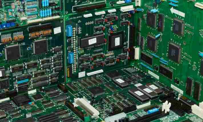
PCB design is very important in product reliability design. EMI considerations for PCB design: Design engineers often pay close attention to the routing of signals on the PCB, but often do not consider their return path. The key to understanding and solving EMI problems is to understand the flow of electricity. Current flows in a loop, so many digital circuit design engineers tend to forget this important fact. Because, most schematic inspections show that half of the schematic forgot the ground or signal and power return system. Therefore, it is easy to overlook all the power supply and signal return path, which is the circuit board routing personnel of the temporary negligence can lead to significant EMI problems.
By understanding how the return current returns to its source and how to ensure that the return path is low impedance, EMI problems in products can be well solved.
First, consider how a high frequency current flows. At low frequencies, the return current usually flows along the path of least resistance. At high frequencies, the return current usually flows along the path with the least impedance. As shown in the picture below. The reason for this phenomenon is that at higher frequencies, when the signal or power conductor or PCB routing and its associated return path - the physical size of another conductor or return plane is the smallest, its path self-induction is minimal. Because of this phenomenon, the result is that the current and return current in the signal or power supply wire usually minimize the physical space between the outgoing current and the input current. If the forced return path forms a large loop area, this loop acts like an antenna and will emit radiation.

When the frequency is greater than 1MHz, the return current usually flows directly on the signal return plane above or below the signal PCB line. This depends on the layer structure of the signal PCB board. If the return path is forced to have a longer path below the line of the signal, the physical size of the loop will become very large, usually resulting in the emission of the ring antenna, as well as the creation of a common-mode voltage source. These voltage sources generate common-mode current around the PCB and usually along an I/O cable or power cable that emits radiation like a mono pole or dipole antenna.
In practical applications, it is often found that the PCB signal and power return plane designed by electronic engineers for their products have animadverted gaps and this leads to a larger return current path. The return current is forced to change the path and the resulting magnetic field around the PCB. A loop antenna is formed when the return current is forced away from the preferred path with the least impedance, as shown in the figure above. This creates magnetic fields around the entire board, which can also be coupled to other PCB wiring, effectively forming small voltage sources, which in turn generate common-mode current around the board. These common-mode currents are then coupled to the I/O cable or power cable, where they radiate high frequency harmonics of the fundamental signal.
Mutual inductance in the return plane produces a small voltage drop AU = L· (DI/at), which produces a common-mode current. Mutual inductance between the signal current loop and another nearby circuit will also produce a voltage difference, which can generate current in a nearby circuit.
Another common problem with EMI generation when PCB wiring is changing the reference plane layer without specifying a closed physical path for the signal PCB routing of the return current. For example, if the signal PCB wiring starts at the top of the reference return plane, passes through the hole, and continues to reference to this same return plane, it is acceptable with no problem.


Just upload Gerber files, BOM files and design files, and the KINGFORD team will provide a complete quotation within 24h.