
Professional PCB manufacturing and assembly
Building 6, Zone 3, Yuekang Road,Bao'an District, Shenzhen, China
+86-13410863085Mon.-Sat.08:00-20:00

Universal board is a standard IC spacing (2.54mm) covered with solder pads, according to their own will to insert components and wired printed circuit boards. Compared with professional PCB board, hole board has the following advantages: low threshold, low cost, easy to use, flexible expansion. For example, in the student electronic design competition, the work usually needs to be finished in a few days against the clock, so most of the use of universal board. Alias: universal board, experiment board, learning board, hole board, dot matrix board.

Advantages of universal circuit board
1. Good reliability
2. It can be kept forever
3, with a certain intensity
4. Small and medium-sized circuits can be built
Disadvantages of universal circuit boards
It needs to be welded. It's a bit difficult
Wiring skills for the front of universal board
Materials: One universal test plate, preferably without holes. Straight through a number of 0.3mm enameled wire, strength permits the case as far as possible to use a little thinner, so as not to affect the insert pin. Glue, soldering iron, knife, etc.
Making steps:
1. Determine the position of each component on the board, and draw the line of each hole (can be crossed) with a pencil on the front side (set the side without copper coating as the front side).
2. Wire on the non-copper surface of the plate to prevent welding from being affected when wiring on the copper surface. Run the enameled wire through the hole and scrape off the insulating paint from the part to be welded with a knife. Solder well with a soldering iron.
3, in front of the painted line neatly placed enameled wire, enameled wire brush a layer of glue.
4. After the glue dries, the components will be installed successfully. Since the enameled wire is very thin, the component can share the welding hole with the enameled wire, which is why I chose the single-hole universal board.
Glue recommended to use tire repair glue, stick firmly and dry quickly.
Welding methods for universal plates
For the layout of components on the universal board, most people are used to "follow the trail", which is to focus on key components such as chips and other components. This method is welding while planning, disorder reflects order, high efficiency. But because beginners lack experience, it is not suitable to use this method, beginners can first do a preliminary layout on paper, and then use a pencil to draw the front of the hole board (component surface), and then can also plan out the wiring, convenient for their own welding.
For the welding method of universal plate, the fine wire mentioned above is generally used for flying wire connection. There is no great skill in flying wire connection, but horizontal and vertical wire routing should be done as far as possible, clean and clear as shown below.
How to choose universal circuit board
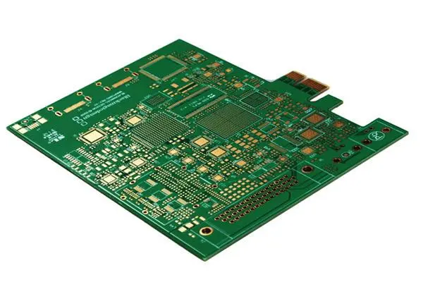
1) There are two main types of hole plate on the market. One type of solder plate is independent: single hole plate; the other is multiple solder plates connected together: even hole plate. Single hole plate is divided into single panel and double panel two. According to the author's experience, single hole board is more suitable for digital circuit and single-chip circuit, even hole board is more suitable for imitation circuit and discrete circuit. Due to the digital circuit and single-chip circuit chip based circuit, circuit more regular; And the imitation circuit and discrete circuit are usually less regular, the pin of the discrete component often needs to connect more than one wire, then if there are more than one pad connected together to facilitate some. Of course, this is not certain, everyone's love is not the same, choose their own to use the contrast is OK.
2) Need to distinguish between two different raw materials of hole plate: copper plate and tin plate. The solder pad of the copper plate is exposed copper and golden yellow. It should usually be wrapped in newspaper to avoid the oxidation of the solder pad. If the solder pad is oxidized, it can be cleaned with a cotton rod dipped in alcohol or scrubbed with a rubber. The surface of the solder plate coated with a layer of tin is tin plate, solder plate silver, tin plate substrate raw material is harder than copper plate, not easy to deformation. Their quotation is also different, taking the single panel of 100 cm2 as an example: copper plate quoted 3 to 4 yuan, tin plate 7 to 8 yuan, usually no more than 8 cents per square centimeter.
The use of universal circuit board is very frequent, so in order to give full play to its role, increase its use value, we must have an overall understanding of it, so as to better serve us.

Manual assembly of adjustable integrated regulated power supply circuit
Electronic practical training teaching is an important link to improve the comprehensive quality of electronic circuit teaching. Through practical training, students can be trained to combine abstract theoretical knowledge with practical circuit closely, and cultivate their knowledge application ability, practical ability and innovation ability. Secondary vocational students' understanding on the analysis of the principle and circuit logic relations lack of interest, so vocational education pays attention to students to do first, he gave me to make a circuit board, debugging, installation unit circuit by circuit state, implement function combination, realize circuit acoustooptic effect, even discharge circuit fault, improve the circuit function gradually stimulate students interest in these processes, build students' sense of accomplishment, and culture It has raised students' professional consciousness and formed students' professional thinking habits.
Many students have learned to delve into professional knowledge after practical training courses, and have formed professional talents skilled in theoretical system operation. They have achieved the ability to improve circuit level, optimize welding quality and innovate circuit system.
Electronic training project and method of many, the use of universal circuit connection circuit training, improve the circuit structure, debugging circuit function is the most commonly used electronic enthusiasts and electronic teaching the early stage of the training methods, and around the primary electronic skills contest in recent years, provincial secondary electronic skills test and secondary single operation assessment of the most common way. Therefore, it has determined its irreplaceable position in vocational electronic training teaching. It is characterized by low cost, flexible use, students can give full play to their subjective initiative, independent design, repeated modification, repeated use. In the process of teaching, teachers in secondary vocational schools design the teaching process scientifically and arrange the teaching content reasonably, which will make the electronic training teaching achieve a very ideal effect.
The first is to determine the content, beginners can not be too complex content, choose a circuit to do the structure and function of clear, clear logic, simple debugging method, familiar with the working principle of components circuit. Generally do not choose those with many functions, large welding components, and weak operability of the circuit. Before determining the project, the instructor must fully understand the knowledge structure of the students and the theoretical teaching progress, and choose the topic from the perspective of practical, intuitive and interesting, which is more conducive to stimulate the students' thirst for knowledge. For example, acousto-optic control circuit, action delay circuit, fault detection circuit, game demonstration circuit, etc.
Again is familiar with the circuit structure, secondary vocational students may not be able to understand the working principle of the circuit, but the circuit components of the circuit symbol, commonly used letters, packaging, shape structure understanding nominal value reading, polarity judgment, performance selection, line connection method must have a system
Only after the basic knowledge of these units is mastered, can the circuit analysis and installation training be carried out. For example, in the schematic diagram of the adjustable integrated regulated power supply circuit, the direction of the six secondary tubes VD1-VD6, the pin sequence of the adjustable integrated LM317, and the polarity of the electrolytic capacitor are shown. However, these knowledge seems to be complex, in fact, it is easy to understand, only need to rely on common professional textbooks, common market electronic components and general voltmeters, ammeters, multimeters can be.
It is also very important to strengthen perceptual knowledge. Before assigning tasks, providing some material objects or video materials for students to establish certain patterns is of great help to provide students' interests
. For example, some finished circuit, universal board view.

Reflection caused by PCB wiring width change
Nov 01,2022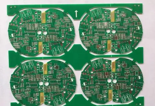


Just upload Gerber files, BOM files and design files, and the KINGFORD team will provide a complete quotation within 24h.