

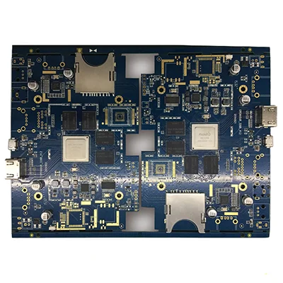
Netcom Prototype PCB Assembly
Name: Netcom Prototype PCB Assembly
Number of SMT lines: 7 high-speed SMT patch supporting production lines
SMT daily production capacity: more than 30 million points
Testing Equipment: X-RAY Tester, First Piece Tester, AOI Automatic Optical Tester, ICT Tester, BGA Rework Station
Placement speed: CHIP component placement speed (at best conditions) 0.036 S/piece
The smallest package that can be attached: 0201, the accuracy can reach ±0.04mm
Minimum device accuracy: PLCC, QFP, BGA, CSP and other devices can be mounted, and the pin spacing can reach ±0.04mm
IC type patch accuracy: it has a high level for mounting ultra-thin PCB boards, flexible PCB boards, gold fingers, etc. Can be mounted/inserted/mixed TFT display driver board, mobile phone motherboard, battery protection circuit and other difficult products
Function
Communication function: support GPRS and short message dual-channel data transmission; support multi-center data communication.
Use function: collect serial device data, such as serial instrument, collector, PLC, etc.
Remote management function: support remote parameter setting, program upgrade
Features
Industrial-grade design, suitable for harsh outdoor environments.
Built-in hardware and software watchdog, no crash, no drop.
Support data transparent transmission.
Support domain name resolution function.
Support various configuration software and users to develop their own software systems.
Advantage
In comparison, using the wireless data transmission module to establish a dedicated wireless data transmission method has the following advantages over other methods. The following introduces the advantages of using a DATA-6106 wireless data transmission module to establish a dedicated wireless data transmission method compared to wired communication.
Cheap
The establishment of wired communication methods requires erecting cables or digging cable trenches, which requires a lot of manpower and material resources; while using wireless data transmission stations to establish dedicated wireless data transmission methods does not require erecting cables or digging cable trenches, and only needs to be connected at each terminal. The wireless data transmission station and the antenna with proper height can be set up. In contrast, using a wireless data transmission module to establish a dedicated wireless data transmission method saves manpower and material resources, and the investment is quite economical.
Of course, in some short-distance data communication systems, the wireless communication method is not less expensive than the wired method, but sometimes the actual on-site environment is difficult to wire, and customers still choose the wireless method to achieve communication according to the needs of the on-site environment.
Short construction period
When it is necessary to connect and communicate with remote sites with a distance of several kilometers to tens of kilometers, using a wired method requires erecting long-distance cables or digging long cable trenches. This project cycle may take several months. However, using the data transmission module to establish a dedicated wireless data transmission method only needs to set up an antenna of appropriate height, and the project cycle only takes a few days or weeks. In contrast, the wireless method can quickly establish a communication link, and the project The cycle is greatly shortened
Good adaptability
The limitations of wired communication are too large. When encountering some special application environments, such as special geographical environments such as mountains, lakes, and forest areas, or application environments where wiring is difficult such as moving objects, the wired network will be limited. Wiring engineering has extremely strong constraints, and the use of wireless data transmission modules to establish dedicated wireless data transmission methods will not be subject to these restrictions, so using wireless data transmission modules to establish dedicated wireless data transmission methods will have better and wider coverage than wired communications. The adaptability is almost not limited by the geographical environment.
Good scalability
After users set up a communication network, they often add new equipment due to the needs of the system. If the wired method is used, re-wiring is required, the construction is more troublesome, and the original communication line may be damaged, but if the wireless data transmission station is used to establish a dedicated wireless data transmission method, it is only necessary to connect the new equipment with the wireless data transmission station. The expansion of the system can be realized by connecting each other, which has better scalability in comparison.
Technical parameter
Data format: 8 data bits, 1 stop bit, parity bit (odd, even, none) can be set.
Baud rate: 300, 600, 1200, 2400, 4800, 9600, 19200 (Bit/S) optional.
Communication error code: ≤10.
Power supply: 10V ~ 30V DC.
Average current: <70mA/12V.
Working environment: Temperature: -40~+85℃; Humidity: ≤95%.
data transmission
Data transmission can be simply divided into wired (including erecting optical cables, cables or leased telecommunication lines) and wireless (divided into establishing dedicated wireless data transmission systems (433MHZ frequency band and 2.4G frequency band) or borrowing CDPD, GSM, CDMA and other public network information platforms ) in two categories.
Application field
Wireless communication modules are widely used in vehicle monitoring, remote control, telemetry, small wireless networks, wireless meter reading, access control systems, community paging, industrial data acquisition systems, wireless tags, identification, non-contact RF smart cards, small wireless data terminals, security Fire protection system, wireless remote control system, biological signal acquisition, hydrometeorological monitoring, robot control, wireless 232 data communication, wireless 485/422 data communication, digital audio, digital image transmission and other fields.
Applications:
The first thing users care about is the transmission distance, but the distance is not a problem. The near one uses the 433MHz frequency band wireless data terminal DTD433, and the far one uses the GPRS transparent transmission data terminal DTP_S09F. The so-called "near" means that most factories and mines can be covered within 3 kilometers; the so-called "far" means that the communication distance exceeds 3 kilometers, even across different regions and different countries. Fortunately, China Mobile's network has covered the whole world, so distance is not a problem . The combination of DTP_S09F and DTD433 can meet the requirements of most wireless measurement and control.
Wireless communication scheme between multiple PLCs
Design instructions for wireless MODBUS communication between multiple Siemens S7_200s, with design instructions and programs for PLC master and slave.
The wireless N:N communication design between multiple Mitsubishi PLCs, Inovance PLC and Mitsubishi PLC have the same solution.
MODBUS wireless communication routine between two Delta PLCs, program source code and design instructions. ◆Connection application between wireless PLC data terminal and wireless MODBUS measurement and control terminal
PLC performs MODBUS protocol wireless communication with 4DI/4DO wireless switch terminal DTD433H and 4AI/4AO wireless analog terminal DTD433F within 3 kilometers to realize wireless MODBUS transmission. ◆Wireless communication scheme between touch screen and PLC
Wireless communication between Siemens 200PLC and wireless PLC data terminal and Shenzhen Kinco touch screen;
Wireless PPI communication between Weilun touch screen and S7-200;
Wireless communication between Kunlun Tongtai touch screen MCGS and PLC;
Wireless MODBUS communication between Autoface touch screen and Siemens PLC;
Display and control touch screen wireless communication example
To run the touch screen configuration program, MODBUS protocol, Siemens PPI protocol, Mitsubishi N:N protocol, FATEK PLC protocol, Delta PLC protocol, etc. can be used. ◆Wireless communication scheme between configuration software and PLC
Wireless PPI and MODBUS communication between Kingview software and Siemens PLC;
Wireless communication between force control configuration software and Siemens PLC;
Precautions
The module must be modulated by signals to work normally. Common fixed-code encoding devices such as PT2262/2272 can be directly connected, which is very simple. Because it is a dedicated encoding chip, the effect is very good and the transmission distance is very long.
Another important use of the module is to cooperate with the single-chip microcomputer to realize data communication. At this time, there are certain skills:
1. Reasonable communication speed
The maximum transmission data rate of the data module is 9.6KBs, which is generally controlled at about 2.5k. If the data rate is too high, it will reduce the receiving sensitivity and increase the bit error rate or even fail to work at all.
2. Reasonable information code format
When the single-chip microcomputer and the module work, they usually define the transmission protocol by themselves. No matter what modulation method is used, the format of the information code to be transmitted is very important, and it will directly affect the reliable sending and receiving of data.
Code group format recommendation scheme
Preamble + synchronization code + data frame, the length of the preamble should be greater than 10ms to avoid background noise, because the first bit of data received by the receiving module is easily interfered (that is, zero-level interference) and the received data mistake. Therefore, using CPU coding and decoding can add some garbled codes before the data identification bit to suppress zero-level interference. The synchronization code is mainly used to distinguish it from the preamble and data. It has certain characteristics, so that the software can identify the synchronization code through a certain algorithm, and at the same time prepare for receiving data.
The data frame should not use non-return-to-zero code, let alone long 0 and long 1. Use Manchester code or POCSAG code, etc.
The interference of the single chip microcomputer to the receiving module
When MCU simulates 2262, it is generally normal. However, when MCU simulates 2272 and decodes, it usually finds that the remote control distance is shortened a lot. This is because the multiplication of the clock frequency of MCU will interfere with the receiving module. The electromagnetic interference of 51 series MCU is relatively large. 2051 Slightly smaller, PIC series is relatively small, we need to take some anti-interference measures to reduce interference. For example, the single-chip microcomputer and the remote control receiving circuit are powered by two 5V power supplies respectively, and the receiving board is powered by a single 78L05, the clock area of the single-chip microcomputer is far away from the receiving module, the operating frequency of the single-chip microcomputer is reduced, and shielding is added in the middle.
It is better to make an isolation circuit when the receiving module interfaces with the 51 series single-chip microcomputer, which can better contain the electromagnetic interference of the single-chip microcomputer to the receiving module.
When the receiving module is working, it generally outputs high-level pulses, not DC levels, so it cannot be tested with a multimeter. When debugging, a light-emitting diode can be connected in series with a 3K resistor to monitor the output status of the module.
When the wireless data module is used with special codec chips such as PT2262/PT2272, the connection is very simple, as long as the direct connection is sufficient, the transmission distance is ideal, and generally can reach more than 600 meters. The clock interference caused by the transmission distance is significantly reduced, and the general practical distance is within 200 meters.
Kingford provides Netcom prototype PCB assembly, short delivery time, professional one-stop PCBA service, welcome to inquire

Name: Netcom Prototype PCB Assembly
Number of SMT lines: 7 high-speed SMT patch supporting production lines
SMT daily production capacity: more than 30 million points
Testing Equipment: X-RAY Tester, First Piece Tester, AOI Automatic Optical Tester, ICT Tester, BGA Rework Station
Placement speed: CHIP component placement speed (at best conditions) 0.036 S/piece
The smallest package that can be attached: 0201, the accuracy can reach ±0.04mm
Minimum device accuracy: PLCC, QFP, BGA, CSP and other devices can be mounted, and the pin spacing can reach ±0.04mm
IC type patch accuracy: it has a high level for mounting ultra-thin PCB boards, flexible PCB boards, gold fingers, etc. Can be mounted/inserted/mixed TFT display driver board, mobile phone motherboard, battery protection circuit and other difficult products
