
Professional PCB manufacturing and assembly
Building 6, Zone 3, Yuekang Road,Bao'an District, Shenzhen, China
+86-13410863085Mon.-Sat.08:00-20:00


We can use flex circuits in a variety of applications. They can be safely bent into small and complex electronics, making them suitable for modern devices such as smartphones. They easily absorb shock and vibration in high stress applications.
Rigid-flex circuits combine standard board construction with flexible designs for situations that require greater durability. Have you thought about the materials and layout involved in creating these versatile PCBs? This blog post will provide a brief overview of common materials and structures in flex and rigid-flex PCBs.

Materials used in flexible circuits
While most standard PCBs have fiberglass or metal substrates, flexible circuit cores are composed of flexible polymers. Most flexible PCBs are based on polyimide (PI) films. PI films do not soften when heated, but remain flexible after heat curing. Many thermoset resins, such as PI, harden when heated, making PI an excellent material in flexible PCB construction. Standard PI film does not have good moisture and tear resistance, but choosing an upgraded PI film can alleviate these problems.
The layers of a flexible PCB also require adhesives or special substrates. Manufacturers previously only used adhesives, but this approach reduced the reliability of the PCB. To address these issues, they developed adhesive-free PI, which attaches to copper without an adhesive. This material enables thinner designs and reduces the risk of via cracking. Instead of using solder mask to cover and protect flex circuits, manufacturers use cover films, also made of PI. If you want an area on a flexible PCB to be rigid, the manufacturer can laminate a stiffer part to that part, but the signal cannot travel between the flexible and rigid parts.
Rigid-Flex Printed Circuit Board Materials
A rigid-flex PCB connects rigid PCB material to flexible material. The result is only flexing in places, making the board stronger but still flexible. If you want signals to travel between rigid and flexible parts, you need to design a rigid-flex PCB. In a rigid-flex design, the flex portion of the board resembles a typical flex circuit. At the same time, the material of the rigid part is similar to that of a standard rigid PCB. Just like a standard PCB, these rigid areas are usually backed by fiberglass. Multilayer rigid-flex PCBs also include prereg fiberglass as an intermediate substrate layer.
Popular stacking for layer flex circuit construction
Single-layer and double-layer flex circuits each have many stack-ups common in electronics. Single-layer flex circuits typically include stiffeners made of pressure-sensitive adhesive (PSA) and FR-4 fiberglass. A few pieces of FR-4 stabilize each end of the PCB, while a thin layer of PSA makes the middle of the board stronger. Since double layer flex PCBs have a variety of computer-related applications, they tend to have zero insertion force (ZIF) connectors. Using PI as a stiffener on the ends gives the board the flexibility it needs to connect to a ZIF connector.
Rigid-flex PCBs come in a variety of structures, but a common approach involves four rigid layers and two flex layers. It includes a core made of glue-free PI to reduce the risk of breakage. Above this layer and its copper film, two layers of prepreg are attached to the cover layer adhesive and cover layer of the bend. Rigid sections accept additional copper, fiberglass and solder mask layers.
The main material of flexible PCB
Oct 22,2022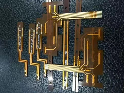


Just upload Gerber files, BOM files and design files, and the KINGFORD team will provide a complete quotation within 24h.