
Professional PCB manufacturing and assembly
Building 6, Zone 3, Yuekang Road,Bao'an District, Shenzhen, China
+86-13410863085Mon.-Sat.08:00-20:00

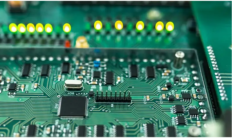
Allegro has now almost become the actual industrial standard in high-speed board design. It is used for high-speed, high-density and multi-layer complex PCB design and wiring. Allegro has the advantages of convenient operation, friendly interface and powerful functions (such as simulation, signal integrity simulation and power integrity simulation) With good integration and many other advantages, it firmly occupies the dominant position in making high-speed PCB boards. In this world, 60% of computer motherboards and 40% of mobile phone motherboards can be drawn by Allegro, which are widely used in the communication field and PC industry. It is known as a popular high-end pcb tool.
Answer: 1. Impedance matching of signal line; 2. Space isolation from other signal lines; 3. For digital high-frequency signals, the differential line will be better.
2. When laying boards, if the lines are dense, there may be more holes, which will certainly affect the electrical performance of the board. How can I improve the electrical performance of the board?
Answer: For low-frequency signals, vias do not matter. For high-frequency signals, vias should be minimized. If there are many lines, multi-layer boards can be considered.
3. Is the more decoupling capacitors added to the board, the better?
Answer: The decoupling capacitor needs to be added with a proper value at a proper position. For example, add it to the power supply port of your analog device, and use different capacitance values to filter out stray signals of different frequencies.
4. What is the standard of a good board?
Answer: The layout is reasonable, the power redundancy of the power line is sufficient, and the high frequency impedance and low frequency wiring are simple
5. How much do through-hole and blind hole affect the difference of signals? What are the principles of application?
Answer: The use of blind holes or buried holes is an effective way to improve the density of multilayer boards, reduce the number of layers and board size, and greatly reduce the number of plated through holes. However, by comparison, through holes are easy to realize in PCB technology, and the cost is low. Therefore, through holes are used in general design.
6. When it comes to analog digital hybrid systems, it is suggested that the electric layer be divided, the ground plane be covered with copper, and it is also suggested that the electric layer be divided, and different grounds be connected at the end of the power source. However, the return path of the signal is far away. How to choose an appropriate method for specific applications?
Answer: If you have a high frequency signal line>20MHz, and the length and quantity are relatively large, you need to give at least two layers of analog high frequency signal. One layer of signal line, one layer of large area, and the signal line layer needs to make enough vias to the ground. The purpose is to:
1. For analog signals, this provides a complete transmission medium and impedance matching;
2. The ground plane isolates analog signals from other digital signals;
3. The ground loop is small enough, because you have punched many vias, and the ground has a large plane.
7. In the circuit board, the signal input plug-in is on the left edge of the PCB and the MCU is on the right. So, in the layout, is it better to place the regulated power supply chip near the source (the power supply IC outputs 5V to the MCU through a long path), or is it better to place the power supply IC to the right in the middle (the power supply IC's output 5V line to the MCU is shorter, but the input power supply line passes through a longer PCB)? Or better PCB layout?
A: First of all, is your so-called signal input plug-in a simulator? If it is a simulator, it is recommended that your power supply layout should not affect the signal integrity of the analog part as much as possible. Therefore, there are several points to consider:
(1) First of all, whether your regulated power supply chip is a clean, low ripple power supply. For the power supply of the analog part, the requirements for the power supply are relatively high;
(2) Whether the analog part and your MCU are the same power supply. In the design of high-precision circuit, it is recommended to separate the power supply of analog part and digital part
(3) The power supply for the digital part needs to consider minimizing the impact on the analog circuit.
8. In the application of high-speed signal link, there are analog ground and digital ground for multiple ASICs, whether to use ground division or not? What are the existing guidelines? Which works better?
A: So far, there is no final conclusion. In general, you can refer to the chip manual. The manual of all mixed chips of ADI recommends a grounding scheme, some of which are recommended for common ground and some for isolation. This depends on the chip design.
9. When should I consider the equality of lines? If equal length wire is considered, what is the maximum length difference between two signal wires? How to calculate?
Answer: Difference line calculation idea: if you transmit a sine signal, your length difference is equal to half of its transmission wavelength, and the phase difference is 180 degrees, then the two signals are completely offset. So the length difference is the maximum. By analogy, the difference between signal lines must be less than this value.
10. In which case is the serpentine routing suitable for high-speed? There are no shortcomings. For example, for differential wiring, two sets of signals are required to be orthogonal.
Answer: The serpentine wiring has different functions due to different applications:
(1) If the serpentine wiring appears in the computer board, it mainly plays a role of filtering inductance and impedance matching, and improves the anti-interference ability of the circuit. The serpentine wiring in the computer motherboard is mainly used in some clock signals, such as PCI-Clk, AGPCIK, IDE, DIMM, etc.
(2) In general, PCB can be used as inductance coil of radio antenna in addition to filtering inductance. For example, 2.4G walkie talkies are used as inductors
(3) The wiring length of some signals must be strictly equal. The equal line length of high-speed digital PCB is to keep the delay difference of each signal within a range and ensure the validity of the data read by the system in the same cycle (when the delay difference exceeds one clock cycle, the data in the next cycle will be misread). For example, there are 13 HUBLinks in the INTELHUB architecture. The frequency of 233MHz is used. They must be strictly equal in length to eliminate hidden dangers caused by time delay. Wire winding is the only solution
Generally, the delay difference is required to be no more than 1/4 clock cycle. The delay difference per unit length is also fixed. The delay is related to the line width, line length, copper thickness, and board structure. However, if the line is too long, the distributed capacitance and inductance will be increased, and the signal quality will be reduced. Therefore, the clock IC pins are generally terminated, but the serpentine wiring does not act as an inductor. On the contrary, inductance will make the higher harmonics in the rising edge of the signal phase shift, resulting in deterioration of the signal quality. Therefore, the serpentine line spacing is required to be at least twice the line width. The smaller the rise time of the signal, the more susceptible to the influence of distributed capacitance and distributed inductance.
(4) Serpentine routing acts as a LC filter with distributed parameters in some special circuits.
11. When designing PCB, how to consider EMC/EMI, and what specific aspects need to be considered? What measures are taken?
Answer: When designing EMI/EMC layout, you must consider the position of components, the arrangement of PCB stacks, the way of important online, and the selection of PCB components.


Just upload Gerber files, BOM files and design files, and the KINGFORD team will provide a complete quotation within 24h.