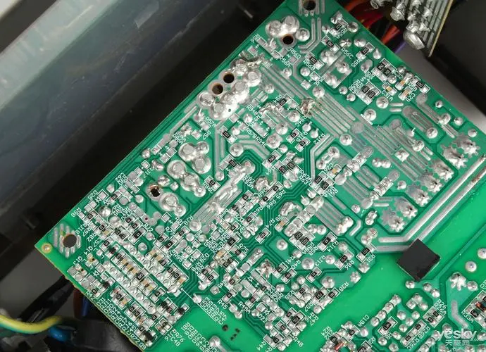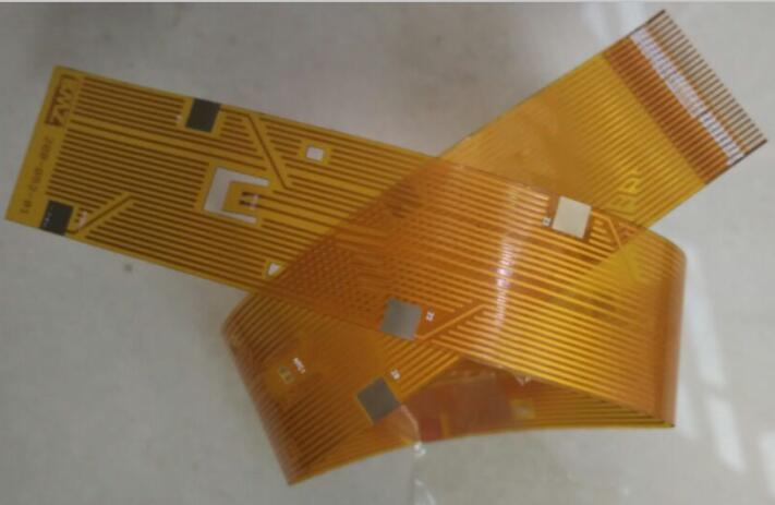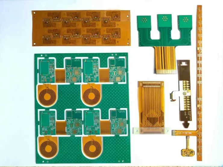
This includes the development of PCBs that drive electronic devices and typically control mechanical and pneumatic operations. Space brings special challenges to manufacturing, which must be overcome to ensure that aerospace systems can safely and reliably complete their tasks. For the manufacture of plates, these are mainly related to the maintenance of structural integrity for changing environmental conditions. PCB assembly is not obvious. However, after defining the development obstacles, we will be able to define a scheme to optimize the aviation PCB assembly to meet the space challenges.
Aerospace pcb design
Space is a challenging environment. It looks peaceful, but it is also dangerous. The temperature range is from more than 1000 degrees Fahrenheit to - 455 degrees Fahrenheit, which imposes enormous mechanical stress on the spacecraft. In addition, there is the possibility of collision of space debris of various sizes. These and other hazards can be classified as external challenges for orbital platforms and spacecraft. As listed below, there are also challenges that threaten the internal systems that aviation system development must face.
Ionic radiation

Radiation is the focus of all vehicles and systems in space. This is more due to its destructive potential for wireless communications than to excessive concentration of destructive power, which may be a biological problem.
RF radiation
RF radiation may also be an important issue. In the atmosphere of the ionosphere, the harm is greatest.
Vibration and mechanical shock
Reusable rockets for space travel are being developed, which will greatly reduce the impact of launch and landing vibrations. Even with these advances, the energy required for launch may still be the source of huge mechanical stress on spacecraft, as well as the vibration source of internal equipment and systems in the future.
environmental control
Due to the limited space of space vehicles and the need for temperature and pressure control, there are fewer heat dissipation options than ground systems.
Extreme temperature
Although extreme temperatures are often associated with external obstacles to the deployment of aerospace systems, internal equipment may also be concerned. For example, the temperature near the engine, which is usually monitored and controlled by electronic devices, can be thousands of degrees Fahrenheit.
In order to successfully deploy spacecraft, the above hazards must be overcome. For circuit board manufacturing, the following methods can be used to select the correct materials to ensure safe operation under thermal, electrical and mechanical environmental conditions. PCBA can also be handled according to the following discussion.
Optimize aerospace PCB assembly to meet space challenges
It is always important that your design be combined with good DFM guidelines. The benefits to PCB development cannot be overstated. However, aerospace applications require much higher quality and reliability than most commercial applications. This is because regulatory requirements typically apply to all aerospace developments, as well as challenges specific to your space system and its deployment. These commands require you to select a qualified contract manufacturer (CM), apply for DFM for aerospace PCB development, employ assembly design (DFA) that meets or exceeds IPC Level 3 electronic assembly standards, and ensure that solder joints and component positions remain complete in space.
One of the biggest challenges that the circuit board on the space shuttle will face is radiation. Whether ion type or RF type, radiation will destroy the circuit board by introducing electromagnetic interference (EMI), thus interfering with signal quality, changing impedance and generating crosstalk on the wiring. Therefore, your design should be optimized for power integrity, incorporate special considerations for signal integrity, and ensure that only high-performance components are used. To facilitate this process, you should use a risk analysis that meets the following conditions: AS9100 includes monitoring and traceability of the supply chain, and adds appropriate additional components, such as shielding, to the assembly process.
The best way to deal with the impact of vibration or mechanical stress that may affect the circuit board is to select materials; However, if your circuit board is flexible or rigid flexible, these impacts may be serious and may cause your circuit board to exceed the bending limit or components to fall off. Ensure that your PCB layout only has a flat component placement position or requires the addition of supports to help assembly, to ensure that good solder joints are formed and components are firmly fixed. For heavier components or where flatness cannot be achieved, it may be necessary to let your CM use stiffeners or increase the adhesion to your flexible plate when assembling.
The temperature of all substances will make them lose their shape or shape. This applies not only to plate materials, but also to components and solder joints. Under normal circumstances, this should not be a problem. As such, it is better to choose the components that will be made of them. NASA Parts Selection List (NPSL). If commercial off the shelf (COTS) components are utilized, you may need to perform AS9102B testing to ensure that the components meet aerospace industry standards.
The PCB design for aerospace applications is different from most other commercial applications. First, industry standards must be met. Then, specific requirements are generated according to the type of space platform and whether it is in orbit or flying in space.


