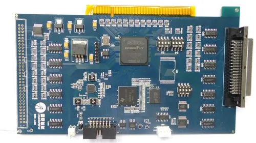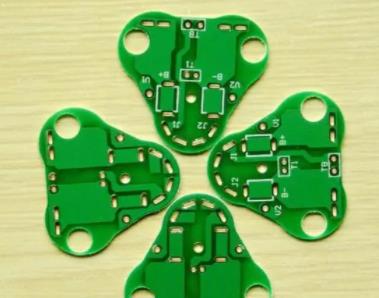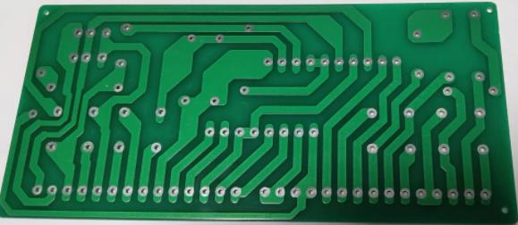
In the lighting and led industries, aluminum substrates are basically used. What are our requirements for PCB design and circuit manufacturing? The following three points are considered: machining, aluminum base surface, and high voltage test.
(1) Machining: It is OK to drill aluminum substrate, but no burr is allowed on the hole edge after drilling, which will affect the withstand voltage test. Milling the profile is very difficult. The shape stamping requires the use of advanced molds. The mold making is very skilled, which is one of the difficulties of aluminum substrate. After the appearance is punched, the edges shall be very neat without any burr, and the PCB solder mask at the board edge shall not be damaged. Usually, the drill die is used. The hole is punched from the line, and the shape is punched from the aluminum surface. When the circuit board is punched, the force is cut up and pulled down. These are all skills. After punching the shape, the warpage of the board shall be less than 0.5%.

(2) The entire production process is not allowed to scratch the aluminum base surface: the aluminum base surface will change color and blacken when touched by hand or by some chemicals, which is absolutely unacceptable. Re polishing the aluminum base surface will not be accepted by customers, so it is one of the difficulties in the production of aluminum base plate not to bump or touch the aluminum base surface in the whole process. Some enterprises adopt passivation process, while others stick protective film before and after hot air leveling (tin spraying)
(3) Overvoltage test: the aluminum substrate of communication power supply requires 100% high-voltage test. Some customers require DC power, some require AC power, and the voltage requires 1500V, 1600V for 5 seconds, 10 seconds. 100% of the printed boards are tested. Dirt, holes and aluminum base edge burrs on the board surface, wire sawtooth, and damage to any small point of insulation layer will lead to fire, electric leakage and breakdown in the high voltage resistance test. The pressure test board shall be rejected for delamination and blistering.
Basic knowledge of iron base plate
In some high-end motor applications, such as motors, high-end PCB products will encounter metal heat dissipation plates, which is what we call iron base plates. At present, iron base plates are widely exported. Let's briefly understand their basic knowledge and process flow.
Iron base plate is a kind of metal heat dissipation base plate applied to high-end motors, high-end product equipment and motors. At present, PCB is widely used in the market and generally exported to Japan, South Korea, Taiwan, Canada and other countries. The hardness of iron base plate is much more difficult to manufacture than aluminum base plate. It is difficult for ordinary manufacturers to master the technology, and the cost and scrap rate are relatively high.
Most iron base plates in the market are single sided aluminum base plate (green oil iron base plate) and double-sided iron base plate, with a thickness of 1mm to 6mm. The iron base plate has a circuit layer: equivalent to copper clad plate of ordinary PCB, and the circuit copper foil thickness is between loz and 8oz.
Iron base plate process is generally: ① Grinding plate (500 # brush) → ② Water washing → ③ Passivation → ④ Water washing × 3 → ⑤ Blow dry → ⑥ Drying, grinding plate: only grinding iron surface, grinding plate according to FR4 parameters. It is required to check that the circuit is free of scratches, tin surface blackening and other defects, and the abrasion marks are even.


