
Professional PCB manufacturing and assembly
Building 6, Zone 3, Yuekang Road,Bao'an District, Shenzhen, China
+86-13410863085Mon.-Sat.08:00-20:00

Three Special Wiring Technologies in PCB Design and Wiring
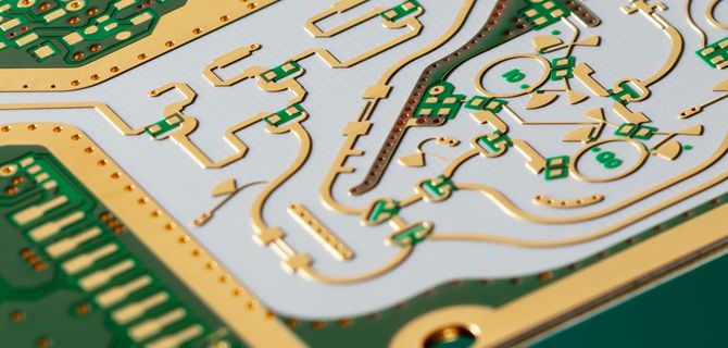
Quality PCB design and routing will directly affect the efficiency of the whole system, and the fastest design theory will eventually be realized and verified through layout It can be seen that wiring is very important in high-speed PCB design The following will analyze the rationality of some situations that may be encountered in actual wiring, and give some optimized routing strategies It is mainly explained from three aspects: right angle routing, differential routing, and serpentine routing
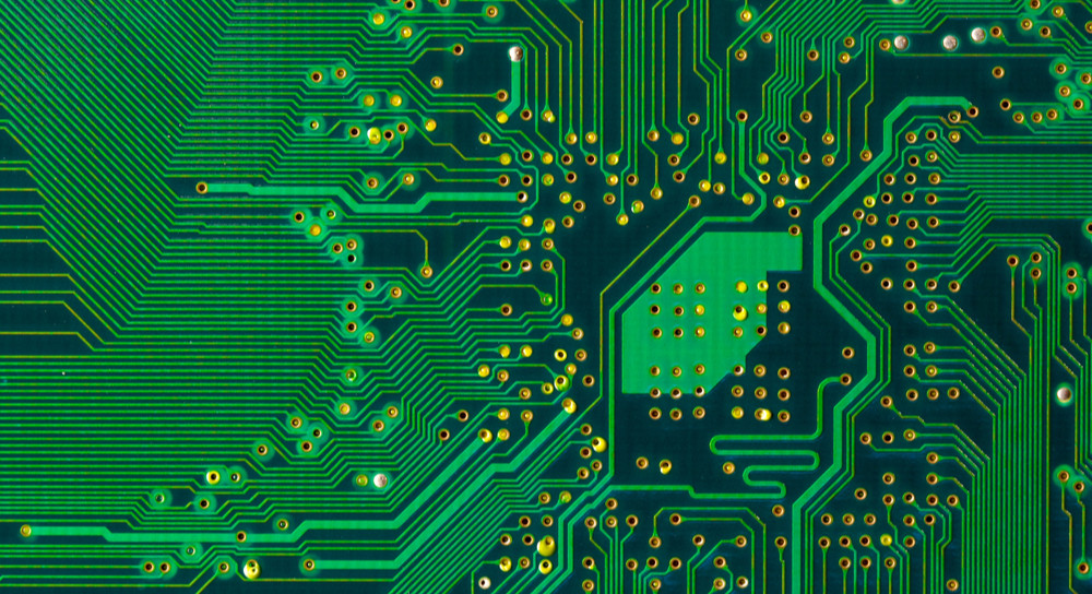
PCB board

1. Right angle trace
Right angle wiring is generally a situation that needs to be avoided as much as possible in PCB wiring How much does right angle wiring affect signal transmission? In principle, the right angle track will change the line width of the transmission line, resulting in impedance discontinuity In fact, not only the right angle trajectory, but also the sharp angle trajectory may cause impedance changes
This impact of the right angle trace on the signal is mainly reflected in three aspects:
(1) The corner can be equivalent to a capacitive load on the transmission line to slow down the rise time;
(2) Impedance continuity will cause signal reflection;
(3) EMI generated at right angles
The parasitic capacitance caused by the right angle of the transmission line can be calculated by the following empirical formula:
C=61W (Er) 1/2/Z0, in the above formula, C refers to the equivalent capacity of the corner (unit: pF), W refers to the width of the trace (unit: inch), 206µ r represents the dielectric constant of the medium, and 2 * C * Z0 is the characteristic impedance of the transmission line For example, for a 4Mils 50 ohm transmission line (Î r is 4.3), the capacitance brought by the right angle is about 0.0101pF, and the resulting rise time change can be estimated as follows: T10-90%=2.2 * C * Z0/2=2.2 * 0.0101 * 50/2=0.556ps It can be seen from the calculation that the capacitance effect caused by the right angle trajectory is very small As the line width of the right angle track increases, the impedance there will decrease, and some signal reflection will occur We can calculate the equivalent impedance after adding the line width according to the impedance calculation formula mentioned in the chapter of transmission line, and then calculate the reflection coefficient according to the empirical formula: = (Zs-Z0)/(Zs+Z0). Generally, the impedance change caused by right angle wiring is between 7% and 20%, so the reflection coefficient is about 0.1. In addition, it can be seen from the figure below that the impedance of W/2 line returns to normal impedance/2 times after W The whole impedance changes in a very short time, usually within 10ps, For ordinary signal transmission, such rapid and small changes can be almost ignored Many people have such an understanding of right angle wiring that it is easy to transmit or receive electromagnetic waves and generate electromagnetic interference, which is one of the reasons why many people believe that right angle wiring is impossible However, many practical test results show that the rectangular trajectory will not produce significant electromagnetic interference compared with straight lines Perhaps the current instrument efficiency and test level limit the testability, but at least it shows a problem that the radiation of the right angle track is less than the measurement error of the instrument itself Generally speaking, right angle wiring is not as terrible as you think At least in applications below GHz, capacitance and other influences, reflection, EMI, etc The TDR test hardly reflects its impact High speed focus PCB design engineers should still be responsible for layout, power/ground design, and tracking design, Through holes and other aspects Of course, although the impact of right angle wiring is not very serious, it does not mean that we can all use right angle wiring in the future Attention to details is the basic quality that every engineer must possess In addition, with the rapid development of digital circuits, PCB engineers will continue to increase the frequency of signal processing. In the RF field, these small right angles may become the focus of high-speed problems
2. Differential trace
Differential signals are more and more wire used in high-speed circuit board design The key signal in the circuit is usually the design of ed with differential structure Why is it so popular? How to ensure its PCB design? We will continue to discuss these two issues in the next part What is differential signal? In layman's terms, the driver sends two equal and opposite signals, and the receiver judges the logic state "0" or "1" by comparing the difference between the two voltages A pair of traces carrying a differential signal is called a differential trace
Different signals have objective advantages in the following three aspects:
A. Strong anti-interference ability, because the coupling between two differential traces is very good When there is noise interference from the outside, they are almost coupled to two wires at the same time, and the receiver only cares about the difference between the two signals In this case, external common mode noise can be completely eliminated
b. It can effectively suppress electromagnetic interference In the same channel, because the polarities of the two signals are opposite, the electromagnetic fields radiated by them can cancel each other The tighter the coupling is, the less electromagnetic energy is released to the outside world
c. Timing positioning, because the switching change of differential signal is located at the intersection of two signals, which is different from the common single ended signal that depends on two threshold voltages, high and low. Therefore, it is less affected by process and temperature, and timing error can be reduced It is also more suitable for circuits with low amplitude signals The current popular LVDS refers to this small amplitude differential signal technology For PCB engineers, the problem is how to ensure that these advantages of differential routing are fully utilized in actual routing Anyone who has been exposed to stacking may understand the general requirements of differential traces, namely "equal length" and "equal spacing". Equal length is to ensure that the two differential signals always maintain opposite polarities and reduce common mode components. Equal distance is mainly to ensure that the differential impedances of the two signals are consistent and reduce reflection. The "as close as possible principle" is sometimes one of the requirements of differential routing But all these rules are not for rhetoric, and many engineers do not seem to understand the nature of high-speed differential signals The following focuses on several common misconceptions in PCB differential signal design
Misunderstanding 1: It is believed that the differential signal does not need the ground plane as the return path, or that the differential path provides a return path for each other This misunderstanding is caused by surface phenomena, or the understanding of high-speed signal transmission mechanism is not deep enough From the structure of the receiver, it can be seen that the emitter currents of transistors Q3 and Q4 are equal and opposite, and their currents at the ground just cancel each other (I1=0). Therefore, the differential circuit is applicable to similar rebound and other possible situations It is insensitive to noise signals on power supply and ground plane Partial echo cancellation of the ground plane does not mean that the differential circuit does not use the reference plane as the signal echo path In fact, in the signal return analysis, the mechanism of differential routing and common single ended routing is the same, that is, high-frequency signals are always the difference between the return currents along the inductor circuit. In addition to the coupling with the ground, differential lines also have mutual coupling No matter which coupling is strong, it will become the main return path
In the circuit design within the printed circuit board, the coupling between differential traces is usually very small, usually accounting for only 10-20% of the coupling degree. More importantly, the coupling with the ground. In conclusion, the main return path of the differential trace still exists in the ground Flat When the local plane is discontinuous, the coupling between differential traces will provide the main return path in the area without reference plane Although the discontinuity of the reference plane will not seriously affect the differential trajectory as the ordinary single ended trajectory, it will still reduce the quality of the differential signal and add EMI, which should be avoided as far as possible Some designers also believe that it is possible to remove the reference plane under the differential trajectory to suppress some common mode signals in differential transmission, but this method is not desirable in theory How to control impedance? Failure to provide a ground impedance loop for common mode signals will inevitably lead to EMI radiation, which will do more harm than good
Myth 2: It is more important to maintain equal spacing than match line length In practice, PCB layout is usually impossible to meet the requirements of differential design Due to factors such as pin distribution, via, and routing space, proper routing must be used to match the line length, but the result must be that some areas of the differential pair cannot be parallel What should we do now? What are the trade-offs? Before reaching a conclusion, let's look at the following analogy From the above analogy results, the waveforms of Scheme 1 and Scheme 2 are almost the same, that is, the influence caused by unequal spacing is minimal In contrast, the impact of line length mismatch on the timing is much greater (Option 3) From the theoretical analysis, although the difference of spacing will lead to the change of differential impedance, because the coupling between differential pairs is not significant, the impedance change range is also very small, usually within 10%, which is equivalent to a pass Reflection caused by holes will not significantly affect signal transmission Once the line length does not match, in addition to timing offset, common mode components are introduced into the differential signal, which will reduce the signal quality and add EMI It can be said that the length of the differential trace on the design PCB matches the line length, and other rules can flexibly handle the design requirements and practical applications as required
3. serpentine
Serpentine line is a type of routing method often used in Layout. Its main purpose is to adjust the delay to meet the system timing design requirements The designer must first understand that the serpentine wire will damage the signal quality, change the transmission delay, and avoid using it when wiring However, in practical design, in order to ensure that signals have sufficient holding time, or to reduce the time offset between signals in the same group, it is usually necessary to deliberately wire So, what effect does the serpentine wire have on signal transmission? What should I pay attention to when wiring? Two key parameters are parallel coupling length and coupling distance Obviously, when the signal is transmitted along the serpentine track, the parallel line segments will be coupled. In the form of differential mode, the smaller S is, the greater Lp is, and the greater the degree of coupling is Due to crosstalk, it may result in reduced transmission delay and greatly reduced signal quality For mechanisms, refer to Common Mode and Differential Mode Crosstalk Analysis in Chapter 3


Just upload Gerber files, BOM files and design files, and the KINGFORD team will provide a complete quotation within 24h.