
Professional PCB manufacturing and assembly
Building 6, Zone 3, Yuekang Road,Bao'an District, Shenzhen, China
+86-13410863085Mon.-Sat.08:00-20:00

A Brief Talk on Some Little Knowledge of PCB
1. Manual welding and rework tools
For PCB boards, manual welding and rework are process steps that require excellent operator skills and good tools; Surface mount manual welding is sometimes more challenging than through hole welding because of smaller pin spacing and higher number of pins In the process of rework, care must be taken not to overheat the printed circuit board; Otherwise, plated through holes and pads are easily damaged Review contact welding and heated gas welding, two common types of manual welding Contact welding is performed when the heated tip or ring is in direct contact with the solder joint The tip or ring is attached to the welding tool The welding joint is used to heat a single welding point, while the welding ring is used to heat multiple welding points at the same time Single nozzle welding tools and welding nozzles have various design structures There are also various designed welding joints in the form of iron ring Discrete rings with two or four sides are mainly used for component disassembly The ring is mainly designed for multi branch components, such as integrated circuits; However, they can also be used to disassemble rectangular and cylindrical components The soldering iron ring is very useful for removing bonded parts After the solder melts, the ring of the soldering iron can twist the parts and disconnect the glue connection Quadrilateral components, such as plastic pin chip carriers, cause problems because it is difficult for the soldering iron ring to contact all pins at the same time If the iron ring does not contact all pins, heat conduction will not occur, which means that some solder joints will not melt Especially on the J pin part, all pins may not be on the same reference plane, making it impossible for the soldering iron ring to contact all pins at the same time This situation can be catastrophic because pads welded to pins will remove components from the PCB board operator Welding joints and welding rings require frequent preventive maintenance They need to be cleaned and sometimes tinned Frequent replacement may be necessary, especially when using small tips Contact welding systems can be classified from low to high, usually limiting or controlling temperature The selection depends on the application For example, surface mount applications typically require less heat than through hole applications
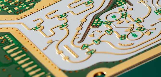
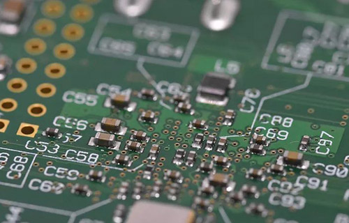
PCB board

A constant temperature system provides continuous and constant output and continuously transfers heat. For surface mount applications, these systems should operate in the temperature range 335 to 365 ° C. Temperature limiting system, which has the temperature limiting ability to help maintain the system temperature within a certain range. These systems transmit heat discontinuously to prevent overheating, but heat recovery may be slow. This may cause the operator to set a higher temperature than required to speed up welding. The operating temperature range for surface mount applications is 285~315 ℃. Control the temperature system and provide high output capacity. These systems, like temperature limiting systems, transfer heat discontinuously. Response time and temperature control are superior to temperature limiting systems. The operating temperature range for surface mount applications is 285~315 ℃. These systems also provide better deflection capability, typically 10 ° C. The characteristics related to contact welding systems include that, in most cases, contact welding is a simple and cost-effective method of repair welding and component disassembly and replacement. Components with glue can be easily removed using welding rings. Contact welding equipment is relatively cheap and easy to obtain. Problems associated with contact welding systems include systems that do not limit the tip or ring, and are susceptible to temperature shocks that raise the tip or ring temperature above the desired range. In order to improve efficiency, the soldering iron ring must be in direct contact with the solder joints and pins. Thermal shock can damage ceramic components, especially multilayer capacitors.
Heated gas (hot air) welding: hot air welding is completed by using a nozzle to guide heated air or inert gas (such as nitrogen) to the solder joints and pins. The selection of hot air equipment ranges from simple handheld devices to heating a single location, to complex automation device design to heating multiple locations. The handheld system removes and replaces rectangular, cylindrical, and other small components. Automation systems remove and replace complex components such as thin feet and area alignment components. The hot air system avoids local thermal stress that may occur in contact with the welding system, making it suitable for applications where uniform heating is essential. The temperature range of hot air is generally 300~400 ℃. The time required to melt the solder depends on the amount of hot air. Larger components may require more than 60 seconds of heating time to remove or replace. Nozzle design is very important; The nozzle must direct hot air to the solder joint, sometimes away from the component body. Nozzles can be complex and expensive. Adequate preventive maintenance is necessary; The nozzle must be cleaned regularly and stored properly to prevent damage. The characteristics related to the hot air system include the low efficiency of hot air as a heat transfer medium and the reduction of thermal shock due to slow heating rate. This is an advantage for some components, such as ceramic capacitors. Hot air is used as the heat transfer medium without direct contact with the tip. The temperature and heating rate are controllable, repeatable and predictable. Issues related to hot air systems include: the price range of hot air welding equipment is medium to high. The automation system is quite complex and requires highly technical operation. Flux and solder. Flux can be dropped in the vial, or sealed or refillable flux pen can be used. Usually, the operator uses too much flow. I prefer to use flux pens because they limit the amount of flux used. I prefer to use flux cored solder, which contains flux and solder alloy. When using flux cored solder and liquid flux, ensure that the flux is compatible with each other. The surface mounting welding usually requires a smaller diameter tin wire, usually within the range of 0.50~0.75mm. Through hole welding usually requires larger diameter tin wire, ranging from 1.20mm to 1.50mm. The solder paste can also be used without a syringe, although many manual welding methods heat the solder paste too fast, resulting in spatter and solder balls. Flux paste, not solder paste, is very useful for aligning components in replacement areas.
2. Etching related proverbs
Side etching: The etching of the side wall of the wire under the resist pattern is called side etching. The degree of side etching is indicated by the width of side etching.
Side etching is related to the type of etching solution, its composition, and the etching process and equipment used.
Etching coefficient: The ratio of wire thickness (excluding coating thickness) to side etching amount is called etching coefficient. Etching coefficient=V/X
Measure the amount of side etching through the level of etching coefficient. The higher the etching factor, the less side etching. In the etching operation of a printed circuit board, it is desirable to have a higher etching coefficient, especially for a printed circuit board with high density thin wires.
Coating widening: in the process of pattern electroplating, because the thickness of the electroplating metal layer exceeds the thickness of the electroplating resist layer, the width of the wire is increased, which is called coating widening.
The widening of the coating is directly related to the thickness of the electroplating resist and the total thickness of the electroplating coating. In actual production, coating widening shall be avoided as much as possible.
Coating edge: the sum of widening and side erosion of metal anti-corrosion coating is called coating edge. If there is no coating widening, the coating protrusion is equal to the side erosion.
Etching rate The depth at which the etching solution dissolves the metal in the tissue time (usually expressed as Î) ¼ M/min) or the time required to dissolve a certain thickness of metal.
Dissolved copper: the amount of copper dissolved in the etching solution at a certain allowable etching rate. It is usually expressed by the number of grams of copper dissolved in each liter of etching solution. For a specific etching solution, its copper solubility is determined.
3. Analysis of the cause of tin free electroplated nickel gold plate
1) Pretreatment for electroplating: acid degreasing. Due to low temperature, there may be some circuit boards or solder mask on the surface nearby/not clean. The concentration/temperature of degreaser can be adjusted, and attention should also be paid to the micro etching depth and uniformity of circuit board color.
2) Nickel plating problem: nickel cylinder is polluted by oil or metal, so it is recommended to use low current electrolysis or carbon core filtration; If the pH value is abnormal, dilute sulfuric acid or nickel carbonate can be used for adjustment; The thickness of nickel plating is not enough and the porosity is too high. Check the current density of nickel plating, check the consistency between the current of conductive rod and the current displayed by the instrument with a current card meter, and check the nickel plating time. If necessary, conduct metallographic sectioning to observe the thickness of nickel layer and the surface condition between layers; If the nickel plating bath additive is low/too high, this may happen, but the low additive may be greater; In addition, the content of nickel chloride also has a certain impact on the solderability of the nickel layer. Pay attention to the adjustment value. Too high stress is high, and too low porosity is high.
3) For false gold plating and nickel coating, the cleaning time is too long or the nickel coating is oxidized and passivated. Pay attention to strengthening the control of the cleaning time. Hot pure water is used here.
4) Poor post-processing; After cleaning, it should be dried in time and placed in a well ventilated place, not in the electroplating workshop.
5) Other should pay attention to all chemical treatments It is recommended not to use urban water/tap water, recycled water/well water, lake water, because the water has high hardness/contains other complex organics and is used for PCB
The above is the explanation given by the editor of pcb circuit board company. If you want to know more about PCBA, you can go to our company's home page to learn about it. In addition, our company also sells various circuit boards,
High frequency circuit board and SMT chip are waiting for your presence again.
AOI Exploration of 6 Sigma PCBA Assembly
Nov 03,2022


Just upload Gerber files, BOM files and design files, and the KINGFORD team will provide a complete quotation within 24h.