
Professional PCB manufacturing and assembly
Building 6, Zone 3, Yuekang Road,Bao'an District, Shenzhen, China
+86-13410863085Mon.-Sat.08:00-20:00


Key Points to Pay Attention to Details in Drawing PCB
Wiring is the most refined and limited technological PCB design process in the world Even engineers who have laid wires for more than ten years often feel that they can't wire because they have seen all kinds of problems and know what will happen if they lay wires As a result, I don't know how to spread it But there are still masters They have very rational knowledge. At the same time, they have some feelings of self creation. The wires they laid are very beautiful and artistic
Here are some good wiring tips and essentials:
First of all, let's make a basic introduction The number of layers of PCB board can be divided into single layer, double layer and multi-layer, and now the single layer is basically eliminated Now, double-layer boards are widely used in audio and communication systems, and they are usually used as power amplifiers Enough From the perspective of through-hole, it can be divided into two through-hole, blind hole and buried hole The through hole is a hole directly from the top layer to the bottom layer; The blind hole passes from the top or bottom layer to the middle layer, and then does not continue to pass The advantage is that the position of the through-hole is not blocked from the beginning to the end Other layers can still be wired at the position of the through-hole; Embedded through-hole means that the through-hole is buried from the middle layer to the middle layer, and the surface is completely invisible Before automatic wiring, the lines with high requirements shall be arranged in advance with interactive pipes. The edges of input and output terminals shall not be adjacent and parallel to avoid reflection interference If necessary, the grounding wire can be added for isolation, and the wiring of two adjacent layers should be perpendicular to each other, because parallel parasitic coupling is easy to occur The routing rate of automatic routing depends on good layout, and routing rules can be preset, such as the number of wire bends, through holes, and steps Generally, exploratory wiring is carried out first, short lines can be quickly connected, and then through labyrinth wiring, the global wiring path is optimized for the wiring to be routed Overall wiring effect For layout, one principle is to separate digital and analog as far as possible, and one principle is that low speed should not be close to high speed The basic principle is to separate digital grounding from analog grounding Because digital grounding is a switching device, the current is large when switching, but small when it does not move Therefore, digital grounding cannot be mixed with analog grounding The recommended layout is shown in the figure below
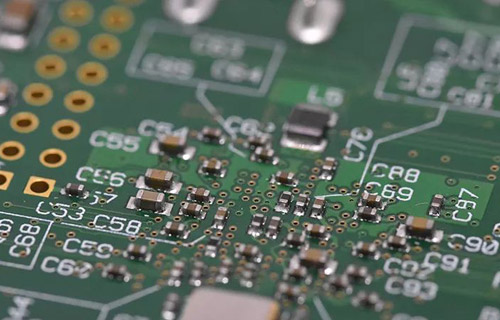
Circuit board
Precautions for wiring between power supply and ground wire
1) A decoupling capacitor should be added between the power supply and the ground wire. The power supply must be connected to the chip pin after passing through the decoupling capacitor The following figure lists several wrong and correct connection methods See Did you make such a mistake? Generally speaking, decoupling capacitors have two functions: one is to instantly provide large current to the chip, and the other is to remove power noise On the one hand, the influence of power noise on the chip should be as small as possible power supply.
2.) Widen the power and ground wires as much as possible. The relationship is: ground wire>power wire>signal wire
3.) You can use a large area of copper layer as the ground wire
2. Processing when digital circuits and analog circuits are mixed
Nowadays, many PCB boards are no longer single functional circuits, but are composed of a mixture of digital circuits and analog circuits. In addition, the mutual interference between them must be considered when wiring, especially the noise interference on the grounding wire. Because of the high frequency of digital circuits and the strong sensitivity of analog circuits, signal lines and high-frequency signal lines should be as far away from sensitive analog circuit equipment as possible, but for the entire PCB board, The grounding wire PCB is not sensitive to the outside. There can only be one node. Recall that the common grounding problem of digital circuit and analog circuit must be in the PCB. Inside the circuit board, the ground of digital circuit and the ground of analog circuit are actually separated, only in the PCB The interface between the board and the outside world (such as a plug, etc.) There is a short circuit between the digital circuit and the analog circuit Please note that there is only one connection point, and some people have no common point in this regard, which depends on the system design
3. Processing of line corners
Usefully there will be changes in the thickness of the corners of the wire It is used to change the thickness of lines. The right angle is bad, the 4.5 degree angle is better, and the round corner is good However, the rounded corner is more troublesome for PCB design. In retrospect, it is usually determined by the signal sensitivity Normally, for ordinary signals, a 45 degree angle is sufficient Only those very sensitive lines need to use rounded corners
4. Check the design rules after wiring
No matter what you do, you must check it after finishing As we do in exams, if we have time, we must check the answers This is an important way for us to get high scores Similarly, we draw PCB boards s In this way, we can be more sure that the circuit board we draw is a qualified product We generally check the following aspects:
1) Whether the distance between wire and wire, wire and through-hole, component pad and through-hole, through-hole and through-hole are reasonable and meet production requirements
2) Which the width of the power line and the ground line is appropriate, whether the power supply and the ground line are tightly coupled (low wave impedance), and whether there are PCB boards anywhere that can broaden the bottom line
3) When measures have been taken for key signal lines, such as short length, new protection lines, and clear separation of input lines and output lines
4) Whether the analog circuit and the digital circuit part have their own independent ground wires.
5) Why the graphics added to the PCB will cause short circuit of signal
6) Modify some unsatisfactory line shapes.
7) Whether there is a process line on the PCB, whether the solder mask meets the production process requirements, whether the size of the solder mask is appropriate, and whether the character logo is pressed on the device keyboard to avoid affecting the quality of electrical equipment
8) When the edge of the outer frame of the power ground layer in the multi layer board is reduced, for example, the copper foil exposed to the power ground layer outside the board is easy to cause short circuit
In a word, the above skills and methods are based on experience, which is a PCB board worth learning from In the process of drawing PCB, in addition to skilled use of drawing tools and software, we must also have solid theoretical knowledge and rich experience Practical experience, which can help you to complete the PCB board quickly and efficiently drawing charts However, it is also very important that you be careful. You must be very careful and careful whether it is wiring or general layout, because your small mistakes may lead to the waste of the final product, and then find nothing wrong. In this case, we prefer to spend more time in the drawing process to carefully check the details, rather than go back to check whether there are problems, which may take more time In short, drawing a PCBpays attention to details


Just upload Gerber files, BOM files and design files, and the KINGFORD team will provide a complete quotation within 24h.