

What is the chip mainly composed of
What is the chip mainly composed of
Why does the led industry use MCPCB
Metal Core PCB Heat Dissipation
Design rules for MCPCB LED board
MCPCB Specifications in LED Technology
The role of MCPCB (metal core PCB) in the Led industry
In today's technological age, the demand for lamps and lighting systems is on the rise. In addition, there are many LED products that are becoming more and more common in the lighting industry. In the past ten years, metal core printed circuit boards have become an integral part of the LED industry. This is no coincidence, as MCPCBs are a unique combination of metal plates, insulating layers, and additional copper foil. In addition, MCPCBs offer a wide range of advantages, including strong magnetic permeability and excellent heat dissipation. However, it is also important to analyze MCPCB boards through the prism of the LED industry. Therefore, in this article, we will take a closer look at the role and use of MCPCB fabrication in the LED industry. —Xiaobei design focus——PCB outsourcing drawing board design. Ten years to raise a person.
Why does the led industry use MCPCB
Custom MCPBCs are ideal for the LED industry for several reasons. First and foremost, the PCB specification includes the ability to integrate dielectric polymer layers. Furthermore, this provides significantly higher thermal conductivity. The domino effect is lower thermal resistance. In addition, LED metal core PCBs heat up at least 8 times faster than FR4 PCBs. In addition, the metal core printed circuit board can play the role of galvanization in the LED industry, because it can be laminated to dissipate heat. This can actually result in a significant reduction in the temperature of the heat-generating components. This feature can yield optimization results, as preservation of LED products and equipment is critical to preventing safety hazards. Furthermore, the prospect of efficient and rapid cooling is crucial to ensure constant light output.
Therefore, the end result is an extended lifetime and performance of LED products.
Metal Core PCB Heat Dissipation
Aluminum PCB has good thermal conductivity. At the same time, MCPCB prototypes (metal core PCB prototypes) have excellent processability and electrical insulation. However, increased demand for LED products has also led to heightened concerns about the outlook for thermal dissipation. Additionally, heat dissipation can degrade the overall performance of the device. Especially those that require high power to run.
This is why proper installation of the MCPCB structure is a key factor in solving this problem.
Many LEDs tend to consume between 2 and 5W. And often fail due to not removing the heat properly. More specifically, LED output is significantly reduced, while heat levels in LED products remain high. This is where the metal core PCB enters the frame. Then, the MCPCB specification can effectively neutralize the heat of all LEDs. This process occurs when the aluminum PCB base and dielectric layer connect the heat sink and IC. Additionally, a radiator is mounted on the main aluminum base. Therefore, this eliminates the need to add an additional number of heat sinks on top of surface added components. Best of all, it's an inexpensive and simple cooling solution.
Design rules for MCPCB LED board
As we said, MCPCB is an integral part of LED technology. Also, the design reason behind this is that the metal core PCB also reduces the number of LEDs needed to generate the lighting. Therefore, MCPCBs are ideal for street lighting, automotive LED applications, and backlight unit applications, among others.
However, it is important for every MCPCB manufacturer (metal core PCB manufacturer) to know certain MCPCB specifications and design rules. At this point, it must be emphasized that MCPCB design rules are similar to conventional PCBs. However, there are various widely used standardized MCPCB design models. Also, most of these MCPCB construction blueprints are based on specific design considerations. The first is to have an extra tooling border around the MCPCB board. Also, this represents a common design pattern per MCPCB specification.
Also, it is recommended to add additional tool holes. The most common designs incorporate 3mm. Besides, tool boundary and tool hole are one of the key elements of MCPCB led design. Combining these two components, the third element is the integration of fiducials into the MCPCB.
MCPCB Specifications in LED Technology
There are a few different MCPCBs in LED technology. Also, construction may vary by manufacturer. So it's safe to say that different versions exist. And most of these models can be modified differently. Also, some MCPCB suppliers tend to modify and adapt structures to suit specific configurations. However, there are some general norms that every professional developer needs to follow. The general specification for metal core PCB/aluminum PCB includes these general parts.
More specifically, the number of layers should be 1-2 layers. Also, it should be combined with a plate thickness of 05.mm, max 3.0mm. As for the thermal conductivity, the general specification is 1.0-4W/mK. Additionally, the specification schematic includes copper thicknesses from 1 to 3 oz.
Additionally, there are other factors to consider:
1: Breakdown voltage: 2-8KV
2: Surface treatment: HAL (lead-free), immersion gold/tin, OSP, gold plating
The LED lighting industry has adopted single-sided or double-sided PCBs.
the bottom line
All in all, the metal core printed circuit board is a major technological innovation. In addition, it is a complete specification for the LED manufacturing process. And, this revolutionary innovation is one of the key components behind the outstanding performance of LED products. After all, using MCPCB led boards in these LED products and applications can greatly reduce the overall heat generated. Therefore, it is safe to say that MCPCB is one of the future-proof innovations.
Background technique:
Japanese Unexamined Patent Application Publication No. 2003-243443 (Patent Document 1) describes a technique for providing a semiconductor device having pads having a simple manufacturing process and excellent adhesion. Specifically, this semiconductor device includes pads for connecting gold wires as bonding wires. In addition, the pad is formed on the flat surface of the insulating layer, and a plurality of recesses are formed in the connection region of the pad connected to the ball portion.
Patent Document 1: Japanese Patent Laid-Open No. 2003-243443
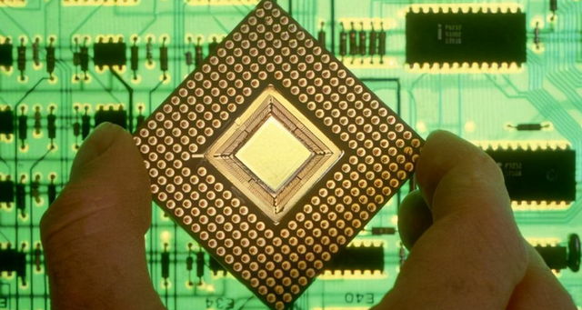
A semiconductor device is composed of a semiconductor chip on which semiconductor elements such as mosfets (metal oxide semiconductor field effect transistors) and multilayer wiring are formed, and a package formed so as to cover the semiconductor chip. The package has the following functions: (1) the function of electrically connecting the semiconductor element formed on the semiconductor chip with the external circuit; (2) protecting the semiconductor chip from the external environment such as humidity and temperature, and preventing damage caused by vibration and shock. The function of destroying and degrading the characteristics of semiconductor chips. Furthermore, the package also has the following functions: (3) the function of making the semiconductor chip easy to handle; (4) the function of dissipating heat generated during the operation of the semiconductor chip and maximizing the function of the semiconductor element.

In packaging, for example, in order to realize the function of electrically connecting a semiconductor element formed on a semiconductor chip with an external circuit, the semiconductor chip is mounted on a wiring member, and the pad formed on the semiconductor chip is connected to the wiring member formed on the wiring member through a wire. terminal connection. That is, the connection between the pad and the terminal is performed by a wire passing through a solder ball.
In the semiconductor device configured in this way, the temperature of the semiconductor device rises due to heat generated by the semiconductor chip during operation, but at this time, it is also required to operate normally within a certain predetermined temperature range. In particular, for semiconductor devices used in automotive products, for example, there are cases where a large current flows for a short period of time, and many of them are placed around high-temperature cabins, and therefore, operation guarantees at higher temperatures than general-purpose semiconductor devices are required more cases. For example, the guaranteed operating temperature of semiconductor devices used in automotive products used to be 125°C, but in recent years, it has gradually been required to be 150°C, and even higher to 175°C.
However, the inventors of the present application made a new finding that in the conventional connection structure using wires via solder balls to connect pads and terminals, the following problems become apparent as the temperature of the semiconductor device rises. That is, in the conventional connection structure, if the temperature is raised, the material constituting the solder ball is likely to diffuse into the material constituting the pad. Alloy layer of material. In addition, if the temperature of the semiconductor device is maintained at a high temperature, the alloy layer will grow and break through the insulating film (glass coating) provided between the pads for insulation. The case of the alloy layer grown on the adjacent pad. At this time, adjacent pads are electrically connected, causing a short-circuit fault. In particular, in recent years, the distance between adjacent pads has become smaller with the advancement of higher functions and miniaturization of semiconductor devices, and thus short-circuit faults are likely to occur. That is, due to the synergistic effect caused by the operation guarantee at high temperature and the narrowing of the pad pitch, it becomes a situation where a short-circuit failure is likely to occur.
- Previous:High Frequency High Speed PCB Design
- Next:No
