

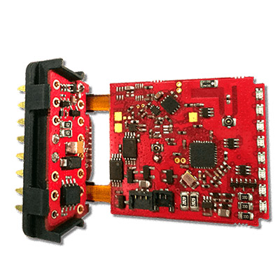
Multilayer Rigid-Flex PCB Assembly
Name:Multilayer Rigid-Flex PCB Assembly
Category:FPC
Description:Basic parameters: Material structure: double-sided adhesive + low loss yellow cover film + (Line copper + plastic + high frequency dielectric polyimide substrate + glue + line copper + Low loss yellow cover film
Tolerance: free bending, folding
Tolerance: ± 0.03mm
Thickness: 0.15mm
Stiffener: positive and negative 0.15mm steel stiffener
Production process: solder coating, plug plating, cover, film type, solder mask type shielded scratch
Surface treatment: Chen Jin (gold) 1 to 2 micro inches
Minimum line width / line distance: 0.06mm / 0.09mm
Other: urgent model after 24-48 hours / normally after 1-3 days shipping
What is a multilayer printed circuit board?
Multilayer printed circuit boards contain three or more conductive layers of copper, usually with plated through holes. If a multilayer circuit board is composed of flexible and rigid materials, it is called a rigid-flex circuit board. A rigid-flex circuit board is a 3D interconnect that can be bent and folded into almost any shape. Rigid-flex technology allows designers to replace multiple PCBs with interconnected wires and/or cables into a single unit, providing improved performance and enhanced readability.
Rigid-flex board technology reduces the need for bulky wiring harness cables in electronic systems. It also saves installation time and parts costs, and results in cleaner (and often more compact) top-of-the-line assemblies.
PCB (Printed Circuit Board) combines the best features of rigid PCB and flexible PCB, making it easier for manufacturers to mount PCBs in tight spaces. The added flexibility enables manufacturers to precisely and easily manipulate the board during installation.
However, before you can take advantage of them, you must first understand and follow the rigid-flex PCB design guidelines. Knowing the trade-off between flexibility and stiffness will help ensure you're not compromising quality either.
What is Rigid-Flex PCB?
As the name suggests, a rigid-flex PCB is a hybrid of flexible and rigid circuits. Their design offers unique solutions and applications as an alternative to rigid PCBs. One of the best aspects of rigid-flex PCBs is that they combine the benefits of both flex and rigid PCBs.
In addition to being used in electronic equipment, rigid-flex circuit boards have a wide range of commercial and industrial applications. They are also used in advanced aircraft-mounted weapons guidance systems; rigid-flex printed circuit boards are widely used in military and avionics manufacturing.
Other rigid-flex PCB applications include:
ABS sensors, CT scans, digital cameras, smart jackets, mobile phones, barcode scanners, pacemakers.
Advantages of rigid-flex PCB
By combining the properties of rigid and flex PCBs, rigid-flex PCBs offer many benefits to manufacturers and consumers.
Mechanical stability: Their basic structure consists of interchanged layers of rigid and flexible PCBs. This ensures they are both stable and flexible for easy installation in tight spaces.
Connection Reliability - With a rigid-flex PCB, you get greater stability and polarity, making connections to other components easier and safer. You also need fewer connector components per application.
Dynamic - In addition to repeatability and precision, you also enjoy greater packaging flexibility.
Cost Effective - By using Rigid-Flex PCBs, you can reduce your overall outlay.
High-Density Applications – Arguably the greatest benefit of rigid-flex PCBs is their use in high-density device populations. This is due to their flexibility, stability and low space usage.
High Shock and Vibration Resistance - Electronic components are used in a wide range of items, some of which experience constant vibration. With such devices, you don't need to worry about damage because the rigid-flex PCB is highly resistant to shock and vibration.
Rigid-Flex PCB Design Guidelines
When you make the switch to rigid-flex PCB design, you need to consider many factors—some old, some new. These include: considering the number of layers, considering proper heat dissipation
Detailed analysis of material layup
1. Consider the number of layers
Rigid-flex PCBs are made from alternating layers of flex and rigid PCB materials. As you prepare to make the switch, determine how many layers your intended use requires. Afterwards, consult with your original equipment manufacturer (OEM) to ensure it meets these requirements.
2. Heat dissipation
When electricity flows through an electronic device, heat is dissipated. The amount of heat released depends on factors such as device characteristics, power, and PCB design. As heat builds, it can affect the performance of your device and can cause damage. Take steps to reduce the amount of heat emitted.
The PCB in the device should facilitate heat dissipation. This can be achieved by adhering to rigid-flex PCB design guidelines.
3. Material layup
For rigid-flex boards, material stackup is a key factor. Obtaining the best stackup requires working closely with your manufacturer on: UL flammability ratings, suitable materials, minimum bend radius required, RoHS certification, impedance control, mechanical considerations, lead-free assembly compatibility, materials Stackup has a big impact on cost, performance and manufacturability.
Dedicate enough time and resources to finding the best layup. After a suitable model has been developed, let the designer do the necessary calculations, which are then verified by the manufacturer.
Boards with different layers can be used. For example, you might have one with 20 layers and another with 12 layers. However, it is important that they have similar layups, similar thicknesses and adhere to flex-rigid design PCB rules. This will help reduce manufacturing issues that can derail a project.
Rigid VS Flex PCB: Which is Better?
The debate between rigid PCBs and flex PCBs has been going on for some time. To determine which is ideal, it's best to first understand how they compare to each other.
First of all, Rigid PCB is the standard type of PCB and is what most people think of when they think of circuit boards. They use conductive tracks and other components laid out on a non-conductive substrate to connect electronic components. Often, non-conductive substrates also contain glass to make the board stronger. In addition to strong support, rigid circuit boards also provide great heat resistance for electronic components.
In addition to rigid and base materials, there are some notable differences between flex and rigid PCBs. These include:
Manufacturing Process: Rigid PCBs are made using a solder mask. However, for flexible PCB designs, a process called overlay or overlay is used. This ensures protection of the exposed circuitry of the flex PCB.
Conductive material: Unlike rigid PCBs, flexible PCB boards should be able to bend. To achieve this feature, flexible rolled annealed copper was used instead of electrodeposited copper as the conductive material.
Cost: Rigid PCBs are less expensive than flex circuit boards. However, when you need a PCB that can fit in tight spaces, you should be willing to incur flexible PCB costs.
How Rigid-Flex PCBs Can Help You
Both rigid and flexible PCBs have unique features that are invaluable for specific applications. However, you are not necessarily limited to one of them. To benefit from the characteristics of both, switch to a rigid-flex PCB. In summary, the benefits of rigid-flex boards include:
Cost-effective, reduced package weight, simplified assembly, can withstand hundreds of bend cycles, increased circuit density, quality is non-negotiable, your manufacturer must be experienced and knowledgeable in rigid-flex PCB design rules. They should also offer personalized customer support and a wide range of design and laying options. This will ensure that your Rigid-Flex PCB meets your needs.

Name:Multilayer Rigid-Flex PCB Assembly
Category:FPC
Description:Basic parameters: Material structure: double-sided adhesive + low loss yellow cover film + (Line copper + plastic + high frequency dielectric polyimide substrate + glue + line copper + Low loss yellow cover film
Tolerance: free bending, folding
Tolerance: ± 0.03mm
Thickness: 0.15mm
Stiffener: positive and negative 0.15mm steel stiffener
Production process: solder coating, plug plating, cover, film type, solder mask type shielded scratch
Surface treatment: Chen Jin (gold) 1 to 2 micro inches
Minimum line width / line distance: 0.06mm / 0.09mm
Other: urgent model after 24-48 hours / normally after 1-3 days shipping
- Previous:No
- Next:6-layer rigid-flex PCB assembly
